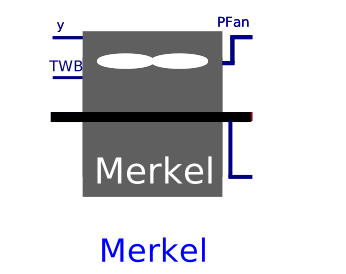
modelMerkel
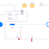
Extends from Buildings.Fluid.HeatExchangers.CoolingTowers.BaseClasses.CoolingTowerVariableSpeed (Base class for cooling towers with variable speed fan).
Information
Model for a steady-state or dynamic cooling tower with a variable speed fan using Merkel's calculation method.
Thermal performance
To compute the thermal performance, this model takes as parameters the nominal water mass flow rate, the water-to-air mass flow ratio at nominal condition, the nominal inlet air wetbulb temperature, and the nominal water inlet and outlet temperatures. Cooling tower performance is modeled using the effectiveness-NTU relationships for various heat exchanger flow regimes.
The total heat transfer between the air and water entering the tower is computed based on Merkel's theory. The fundamental basis for Merkel's theory is that the steady-state total heat transfer is proportional to the difference between the enthalpy of air and the enthalpy of air saturated at the wetted-surface temperature. This is represented by
dQ̇total = UdA/cp (hs - ha),
where hs is the enthalpy of saturated air at the wetted-surface temperature, ha is the enthalpy of air in the free stream, cp is the specific heat of moist air, U is the cooling tower overall heat transfer coefficient, and A is the heat transfer surface area.
The model also treats the moist air as an equivalent gas with a mean specific heat cpe defined as
cpe = Δh / ΔTwb,
where Δh and ΔTwb are the enthalpy difference and wetbulb temperature difference, respectively, between the entering and leaving air.
For off-design conditions, Merkel's theory is modified to include Sheier's adjustment factors that change the current UA value. The three adjustment factors, based on the current wetbulb temperature, air flow rates, and water flow rates, are used to calculate the UA value as
UAe = UA0 · fUA,wetbulb · fUA,airflow · fUA,waterflow,
where UAe and UA0 are the equivalent and design overall heat transfer coefficent-area products, respectively. The factors fUA,wetbulb, fUA,airflow, and fUA,waterflow adjust the current UA value for the current wetbulb temperature, air flow rate, and water flow rate, respectively. These adjustment factors are third-order polynomial functions defined as
fUA,x = cx,0 + cx,1 x + cx,2 x2 + cx,3 x3,
where x = {(T0,wetbulb - Twetbulb),
ṁair ⁄ ṁ0,air,
ṁwat ⁄ ṁ0,wat}
for the respective adjustment factor, and the
coefficients cx,0, cx,1, cx,2, and cx,3
are the user-defined
values for the respective adjustment factor functions obtained from
Buildings.Fluid.HeatExchangers.CoolingTowers.Data.Merkel.BaseClasses.UACorrection.
By changing the parameter UACor, the
user can update the values in this record based on the performance characteristics of
their specific cooling tower.
Comparison with the cooling tower model of EnergyPlus
This model is similar to the model CoolingTower:VariableSpeed:Merkel
that is implemented in the EnergyPlus building energy simulation program version 8.9.0.
The main differences are:
- Not implemented are the basin heater power consumption and the make-up water usage.
- The model has no built-in control to switch individual cells of the tower on or off. To switch cells on or off, use multiple instances of this model, and use your own control law to compute the input signal y.
Assumptions
The following assumptions are made with Merkel's theory and this implementation:
- The moist air enthalpy is a function of wetbulb temperature only.
- The wetted surface temperature is equal to the water temperature.
- Cycle losses are not taken into account.
References
EnergyPlus 8.9.0 Engineering Reference, March 23, 2018.
Parameters
| Type | Name | Default | Description |
|---|---|---|---|
| Boolean | homotopyInitialization (from TwoPortHeatMassExchanger) | true | = true, use homotopy method |
| Data.Merkel.Generic | dat | Performance data | |
| Modelica.Units.SI.HeatFlowRate | Q_flow_nominal | dat.Q_flow_nominal | Nominal heat transfer, (negative) |
| Modelica.Units.SI.ThermalConductance | UA_nominal | per.UA_nominal | Thermal conductance at nominal flow, used to compute heat capacity |
| Real | eps_nominal | per.eps_nominal | Nominal heat transfer effectiveness |
| Real | NTU_nominal | per.NTU_nominal | Nominal number of transfer units |
| Assumptions | |||
| Boolean | allowFlowReversal (from PartialTwoPort) | true | = false to simplify equations, assuming, but not enforcing, no flow reversal |
| Nominal condition | |||
| Modelica.Units.SI.MassFlowRate | m_flow_nominal (from PartialTwoPortInterface) | Nominal mass flow rate | |
| Modelica.Units.SI.PressureDifference | dp_nominal (from TwoPortFlowResistanceParameters) | Pressure difference | |
| Advanced | |||
| Modelica.Units.SI.MassFlowRate | m_flow_small (from PartialTwoPortInterface) | 1E-4*abs(m_flow_nominal) | Small mass flow rate for regularization of zero flow |
| Advanced › Diagnostics | |||
| Boolean | show_T (from PartialTwoPortInterface) | false | = true, if actual temperature at port is computed |
| Flow resistance | |||
| Boolean | computeFlowResistance (from TwoPortFlowResistanceParameters) | true | =true, compute flow resistance. Set to false to assume no friction |
| Boolean | from_dp (from TwoPortFlowResistanceParameters) | false | = true, use m_flow = f(dp) else dp = f(m_flow) |
| Real | n (from TwoPortFlowResistanceParameters) | 2 | Flow exponent, n=1 for laminar, n=2 for turbulent |
| Boolean | linearizeFlowResistance (from TwoPortFlowResistanceParameters) | false | = true, use linear relation between m_flow and dp for any flow rate |
| Real | deltaM (from TwoPortFlowResistanceParameters) | 0.1 | Fraction of nominal flow rate where flow transitions to laminar |
| Dynamics › Nominal condition | |||
| Modelica.Units.SI.Time | tau (from TwoPortHeatMassExchanger) | 30 | Time constant at nominal flow (if energyDynamics <> SteadyState) |
| Dynamics › Conservation equations | |||
| Modelica.Fluid.Types.Dynamics | energyDynamics (from TwoPortHeatMassExchanger) | Modelica.Fluid.Types.Dynamics.DynamicFreeInitial | Type of energy balance: dynamic (3 initialization options) or steady state |
| Initialization | |||
| Medium.AbsolutePressure | p_start (from TwoPortHeatMassExchanger) | Medium.p_default | Start value of pressure |
| Medium.Temperature | T_start (from TwoPortHeatMassExchanger) | Medium.T_default | Start value of temperature |
| Medium.MassFraction[Medium.nX] | X_start (from TwoPortHeatMassExchanger) | Medium.X_default | Start value of mass fractions m_i/m |
| Medium.ExtraProperty[Medium.nC] | C_start (from TwoPortHeatMassExchanger) | fill(0, Medium.nC) | Start value of trace substances |
| Fan | |||
| Modelica.Units.SI.Power | PFan_nominal (from CoolingTowerVariableSpeed) | Fan power at full speed | |
| Real | yMin (from CoolingTowerVariableSpeed) | 0.3 | Minimum control signal until fan is switched off (used for smoothing between forced and free convection regime) |
| cha.fan | fanRelPow (from CoolingTowerVariableSpeed) | Fan relative power consumption as a function of control signal, fanRelPow=P(y)/P(y=1) | |
Connectors
| Type | Name | Default | Description |
|---|---|---|---|
| Modelica.Fluid.Interfaces.FluidPort_a | port_a (from PartialTwoPort) | Fluid connector a (positive design flow direction is from port_a to port_b) | |
| Modelica.Fluid.Interfaces.FluidPort_b | port_b (from PartialTwoPort) | Fluid connector b (positive design flow direction is from port_a to port_b) | |
| Modelica.Blocks.Interfaces.RealOutput | TLvg (from CoolingTower) | Leaving water temperature | |
| Modelica.Blocks.Interfaces.RealInput | y (from CoolingTowerVariableSpeed) | Fan control signal | |
| Modelica.Blocks.Interfaces.RealOutput | PFan (from CoolingTowerVariableSpeed) | Electric power consumed by fan | |
| Modelica.Blocks.Interfaces.RealInput | TWetBul | Entering air wet bulb temperature |
Components
| Type | Name | Default | Description |
|---|---|---|---|
| Modelica.Units.SI.MassFlowRate | m_flow (from PartialTwoPortInterface) | port_a.m_flow | Mass flow rate from port_a to port_b (m_flow > 0 is design flow direction) |
| Modelica.Units.SI.PressureDifference | dp (from PartialTwoPortInterface) | port_a.p - port_b.p | Pressure difference between port_a and port_b |
| Medium.ThermodynamicState | sta_a (from PartialTwoPortInterface) | if allowFlowReversal then Medium.setState_phX(port_a.p, noEvent(actualStream(port_a.h_outflow)), noEvent(actualStream(port_a.Xi_outflow))) else Medium.setState_phX(port_a.p, noEvent(inStream(port_a.h_outflow)), noEvent(inStream(port_a.Xi_outflow))) | Medium properties in port_a |
| Medium.ThermodynamicState | sta_b (from PartialTwoPortInterface) | if allowFlowReversal then Medium.setState_phX(port_b.p, noEvent(actualStream(port_b.h_outflow)), noEvent(actualStream(port_b.Xi_outflow))) else Medium.setState_phX(port_b.p, noEvent(port_b.h_outflow), noEvent(port_b.Xi_outflow)) | Medium properties in port_b |
| Buildings.Fluid.MixingVolumes.MixingVolume | vol (from TwoPortHeatMassExchanger) | ||
| Buildings.Fluid.FixedResistances.PressureDrop | preDro (from TwoPortHeatMassExchanger) | Flow resistance | |
| Modelica.Units.SI.HeatFlowRate | Q_flow (from CoolingTower) | preHea.Q_flow | Heat input into water circuit |
Revisions
-
April 22, 2026, by Michael Wetter:
Removed parameterfraPFan_nominaland introduced instead the non-dimensional parameterdat.PEle_Q_flow_nominal.
This is for #4443. -
April 17, 2025, by Michael Wetter:
Corrected computation of nominal UA value, which also needs to include the correction forcpEqu_nominal.
This is for #4189. -
January 16, 2020, by Michael Wetter:
Revised model to put the thermal performance in a separate block. -
January 10, 2020, by Michael Wetter:
Revised model, changed parameters to make model easier to use with design data. -
October 22, 2019, by Yangyang Fu:
First implementation.