modelWetCoilEffectivenessNTU
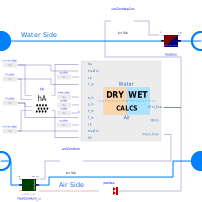
Extends from Buildings.Fluid.Interfaces.PartialFourPortInterface (Partial model with four ports and declaration of quantities that are used by many models), Buildings.Fluid.Interfaces.FourPortFlowResistanceParameters (Parameters for flow resistance for models with four ports).
Information
This model describes a cooling coil applicable for fully-dry, partially-wet, and fully-wet regimes. The model is developed for counter flow heat exchangers but is also applicable for the cross-flow configuration, although in the latter case it is recommended to have more than four tube rows (Elmahdy and Mitalas, 1977 and Braun, 1988). The model can also be used for a heat exchanger which acts as both heating coil (for some period of time) and cooling coil (for the others). However, it is not recommended to use this model for heating coil only or for cooling coil with no water condensation because for these situations, Buildings.Fluid.HeatExchangers.DryCoilEffectivenessNTU computes faster.
Main equations
The coil model consists of two-equation sets, one for the fully-dry mode and the other for the fully-wet mode. For the fully-dry mode, the ε-NTU approach (Elmahdy and Mitalas, 1977) is used. For the fully-wet mode, equations from Braun (1988) and Mitchell and Braun (2012a and b), which are essentially the extension of the ε-NTU approach to simultaneous sensible and latent heat transfer, are utilized. The equation sets are switched depending on the switching criteria described below that determines the right mode based on a coil surface temperature and dew-point temperature for the air at the inlet of the coil. The transition regime between the two modes, which represents the partially-wet and partially-dry coil, is approximated by employing a fuzzy modeling approach, so-called Takagi-Sugeno fuzzy modeling (Takagi and Sugeno, 1985), which provides a continuously differentiable model that can cover all fully-dry, partially-wet, and fully-wet regimes.
The switching rules are:
- R1: If the coil surface temperature at the air inlet is lower than the dew-point temperature of air at inlet, then the cooling coil surface is fully-wet.
- R2: If the coil surface temperature at the air outlet is higher than the dew-point temperature of air at inlet, then the cooling coil surface is fully-dry.
- R3: If any of the conditions in R1 or R2 is not satisfied, then the cooling coil surface is partially wet.
For more detailed descriptions of the fully-wet coil model and the fuzzy modeling approach, see Buildings.Fluid.HeatExchangers.BaseClasses.WetCoilWetRegime. and Buildings.Fluid.HeatExchangers.BaseClasses.WetCoilDryWetRegime.
Assumptions and limitations
This model contains the following assumptions and limitations:
Medium 2 must be air due to the use of various psychrometric functions.
When parameterizing this model with rated conditions (with the parameter
use_UA_nominal set to false), those should
correspond to a fully-dry or a fully-wet coil regime, because
the model uncertainty yielded by partially-wet rated conditions
has not been assessed yet.
The model uses steady-state physics. That is, no dynamics associated with water and coil materials are considered.
The Lewis number, which relates the mass transfer coefficient to the heat transfer coefficient, is assumed to be 1.
The model is not suitable for a cross-flow heat exchanger of which the number of passes is less than four.
By default, the flow regime, such as counter flow or parallel flow,
is kept constant based on the parameter value configuration.
If a flow reverses direction, it is not changed, e.g.,
a heat exchanger does not change from counter flow to parallel flow
if one flow changes direction.
To dynamically change the flow regime,
set the constant use_dynamicFlowRegime to
true.
However, use_dynamicFlowRegime=true
can cause slower simulation due to events.
Validation
Validation results can be found in Buildings.Fluid.HeatExchangers.Validation.WetCoilEffectivenessNTU.
References
Braun, James E. 1988. "Methodologies for the Design and Control of Central Cooling Plants". PhD Thesis. University of Wisconsin - Madison. Available online.
Mitchell, John W., and James E. Braun. 2012a. Principles of heating, ventilation, and air conditioning in buildings. Hoboken, N.J.: Wiley.
Mitchell, John W., and James E. Braun. 2012b. "Supplementary Material Chapter 2: Heat Exchangers for Cooling Applications". Excerpt from Principles of heating, ventilation, and air conditioning in buildings. Hoboken, N.J.: Wiley. Available online.
Elmahdy, A.H. and Mitalas, G.P. 1977. "A Simple Model for Cooling and Dehumidifying Coils for Use In Calculating Energy Requirements for Buildings". ASHRAE Transactions. Vol.83. Part 2. pp. 103-117.
Takagi, T. and Sugeno, M., 1985. Fuzzy identification of systems and its applications to modeling and control. IEEE transactions on systems, man, and cybernetics, (1), pp.116-132.
Parameters
| Type | Name | Default | Description |
|---|---|---|---|
| Boolean | use_dynamicFlowRegime | false | If true, flow regime is determined using actual flow rates |
| Buildings.Fluid.Types.HeatExchangerConfiguration | configuration | Buildings.Fluid.Types.HeatExchangerConfiguration.CounterFlow | Heat exchanger configuration |
| Assumptions | |||
| Boolean | allowFlowReversal1 (from PartialFourPort) | true | = false to simplify equations, assuming, but not enforcing, no flow reversal for medium 1 |
| Boolean | allowFlowReversal2 (from PartialFourPort) | true | = false to simplify equations, assuming, but not enforcing, no flow reversal for medium 2 |
| Nominal condition | |||
| Modelica.Units.SI.MassFlowRate | m1_flow_nominal (from PartialFourPortInterface) | Nominal mass flow rate | |
| Modelica.Units.SI.MassFlowRate | m2_flow_nominal (from PartialFourPortInterface) | Nominal mass flow rate | |
| Modelica.Units.SI.PressureDifference | dp1_nominal (from FourPortFlowResistanceParameters) | Pressure difference | |
| Modelica.Units.SI.PressureDifference | dp2_nominal (from FourPortFlowResistanceParameters) | Pressure difference | |
| Advanced | |||
| Medium1.MassFlowRate | m1_flow_small (from PartialFourPortInterface) | 1E-4*abs(m1_flow_nominal) | Small mass flow rate for regularization of zero flow |
| Medium2.MassFlowRate | m2_flow_small (from PartialFourPortInterface) | 1E-4*abs(m2_flow_nominal) | Small mass flow rate for regularization of zero flow |
| Advanced › Diagnostics | |||
| Boolean | show_T (from PartialFourPortInterface) | false | = true, if actual temperature at port is computed |
| Flow resistance › Medium 1 | |||
| Boolean | computeFlowResistance1 (from FourPortFlowResistanceParameters) | true | =true, compute flow resistance. Set to false to assume no friction |
| Boolean | from_dp1 (from FourPortFlowResistanceParameters) | false | = true, use m_flow = f(dp) else dp = f(m_flow) |
| Real | n1 (from FourPortFlowResistanceParameters) | 2 | Flow exponent for side 1, n=1 for laminar, n=2 for turbulent |
| Boolean | linearizeFlowResistance1 (from FourPortFlowResistanceParameters) | false | = true, use linear relation between m_flow and dp for any flow rate |
| Real | deltaM1 (from FourPortFlowResistanceParameters) | 0.1 | Fraction of nominal flow rate where flow transitions to laminar |
| Flow resistance › Medium 2 | |||
| Boolean | computeFlowResistance2 (from FourPortFlowResistanceParameters) | true | =true, compute flow resistance. Set to false to assume no friction |
| Boolean | from_dp2 (from FourPortFlowResistanceParameters) | false | = true, use m_flow = f(dp) else dp = f(m_flow) |
| Real | n2 (from FourPortFlowResistanceParameters) | 2 | Flow exponent for side 2, n=1 for laminar, n=2 for turbulent |
| Boolean | linearizeFlowResistance2 (from FourPortFlowResistanceParameters) | false | = true, use linear relation between m_flow and dp for any flow rate |
| Real | deltaM2 (from FourPortFlowResistanceParameters) | 0.1 | Fraction of nominal flow rate where flow transitions to laminar |
| Heat transfer › Nominal condition | |||
| Real | r_nominal | 2/3 | Ratio between air-side and water-side convective heat transfer coefficient |
| Heat transfer | |||
| Real | n_w | 0.85 | Water-side exponent for convective heat transfer coefficient, h~m_flow^n_w |
| Real | n_a | 0.8 | Air-side exponent for convective heat transfer coefficient, h~m_flow^n_a |
| Nominal thermal performance | |||
| Boolean | use_Q_flow_nominal | false | Set to true to specify Q_flow_nominal and inlet conditions, or to false to specify UA_nominal |
| Modelica.Units.SI.HeatFlowRate | Q_flow_nominal | Nominal heat flow rate (positive for heat transfer from 1 to 2) | |
| Modelica.Units.SI.Temperature | T_a1_nominal | Water inlet temperature at a rated condition | |
| Modelica.Units.SI.Temperature | T_a2_nominal | Air inlet temperature at a rated condition | |
| Modelica.Units.SI.MassFraction | w_a2_nominal | Humidity ratio of inlet air at a rated condition (in kg/kg dry air) | |
| Modelica.Units.SI.ThermalConductance | UA_nominal | Thermal conductance at nominal flow, used to compute heat capacity | |
| Dynamics › Conservation equations | |||
| Modelica.Fluid.Types.Dynamics | energyDynamics | Modelica.Fluid.Types.Dynamics.SteadyState | Type of energy balance: dynamic (3 initialization options) or steady state |
Connectors
| Type | Name | Default | Description |
|---|---|---|---|
| Modelica.Fluid.Interfaces.FluidPort_a | port_a1 (from PartialFourPort) | Fluid connector a1 (positive design flow direction is from port_a1 to port_b1) | |
| Modelica.Fluid.Interfaces.FluidPort_b | port_b1 (from PartialFourPort) | Fluid connector b1 (positive design flow direction is from port_a1 to port_b1) | |
| Modelica.Fluid.Interfaces.FluidPort_a | port_a2 (from PartialFourPort) | Fluid connector a2 (positive design flow direction is from port_a2 to port_b2) | |
| Modelica.Fluid.Interfaces.FluidPort_b | port_b2 (from PartialFourPort) | Fluid connector b2 (positive design flow direction is from port_a2 to port_b2) |
Components
| Type | Name | Default | Description |
|---|---|---|---|
| Medium1.MassFlowRate | m1_flow (from PartialFourPortInterface) | port_a1.m_flow | Mass flow rate from port_a1 to port_b1 (m1_flow > 0 is design flow direction) |
| Modelica.Units.SI.PressureDifference | dp1 (from PartialFourPortInterface) | port_a1.p - port_b1.p | Pressure difference between port_a1 and port_b1 |
| Medium2.MassFlowRate | m2_flow (from PartialFourPortInterface) | port_a2.m_flow | Mass flow rate from port_a2 to port_b2 (m2_flow > 0 is design flow direction) |
| Modelica.Units.SI.PressureDifference | dp2 (from PartialFourPortInterface) | port_a2.p - port_b2.p | Pressure difference between port_a2 and port_b2 |
| Medium1.ThermodynamicState | sta_a1 (from PartialFourPortInterface) | if allowFlowReversal1 then Medium1.setState_phX(port_a1.p, noEvent(actualStream(port_a1.h_outflow)), noEvent(actualStream(port_a1.Xi_outflow))) else Medium1.setState_phX(port_a1.p, inStream(port_a1.h_outflow), inStream(port_a1.Xi_outflow)) | Medium properties in port_a1 |
| Medium1.ThermodynamicState | sta_b1 (from PartialFourPortInterface) | if allowFlowReversal1 then Medium1.setState_phX(port_b1.p, noEvent(actualStream(port_b1.h_outflow)), noEvent(actualStream(port_b1.Xi_outflow))) else Medium1.setState_phX(port_b1.p, port_b1.h_outflow, port_b1.Xi_outflow) | Medium properties in port_b1 |
| Medium2.ThermodynamicState | sta_a2 (from PartialFourPortInterface) | if allowFlowReversal2 then Medium2.setState_phX(port_a2.p, noEvent(actualStream(port_a2.h_outflow)), noEvent(actualStream(port_a2.Xi_outflow))) else Medium2.setState_phX(port_a2.p, inStream(port_a2.h_outflow), inStream(port_a2.Xi_outflow)) | Medium properties in port_a2 |
| Medium2.ThermodynamicState | sta_b2 (from PartialFourPortInterface) | if allowFlowReversal2 then Medium2.setState_phX(port_b2.p, noEvent(actualStream(port_b2.h_outflow)), noEvent(actualStream(port_b2.Xi_outflow))) else Medium2.setState_phX(port_b2.p, port_b2.h_outflow, port_b2.Xi_outflow) | Medium properties in port_b2 |
| Modelica.Units.SI.HeatFlowRate | Q1_flow | -dryWetCalcs.QTot_flow | Heat input into water stream (positive if air is cooled) |
| Modelica.Units.SI.HeatFlowRate | Q2_flow | dryWetCalcs.QTot_flow | Total heat input into air stream (negative if air is cooled) |
| Modelica.Units.SI.HeatFlowRate | QSen2_flow | dryWetCalcs.QSen_flow | Sensible heat input into air stream (negative if air is cooled) |
| Modelica.Units.SI.HeatFlowRate | QLat2_flow | Buildings.Utilities.Psychrometrics.Constants.h_fg*mWat_flow | Latent heat input into air (negative if air is dehumidified) |
| Real | SHR | QSen2_flow/noEvent(if (Q2_flow > 1E-6 or Q2_flow < -1E-6) then Q2_flow else 1) | Sensible to total heat ratio |
| Modelica.Units.SI.MassFlowRate | mWat_flow | dryWetCalcs.mCon_flow | Water flow rate of condensate removed from the air stream |
| Real | dryFra | dryWetCalcs.dryFra | Dry fraction, 0.3 means condensation occurs at 30% heat exchange length from air inlet |
Revisions
-
June 22, 2026, by Michael Wetter:
Updated Dialog annotations, and revised heat exchanger models to consistently expose parametersr_nominal,n_wandn_a.
This is for #4620. -
March 31, 2026, by Michael Wetter:
Corrected unit propagation error that causes Dymola 2026x to not show certain units.
See #2100. -
February 7, 2025, by Jelger Jansen:
Removedimportstatement. This is for IBPSA, #1961. -
February 3, 2023, by Jianjun Hu:
AddednoEvent()in the assertion function to avoid Optimica to not converge.
This is for issue 1690. -
January 24, 2023, by Hongxiang Fu:
SetflowRegimeto be equal toflowRegime_nominalby default. Added an assertion warning to inform the user about how to change this behaviour if the flow direction does need to change.
This is for issue 1682. -
March 3, 2022, by Michael Wetter:
RemovedmassDynamics.
This is for issue 1542. -
November 2, 2021, by Michael Wetter:
Corrected unit assignment during the model instantiation.
This is for issue 2710. -
Jan 21, 2021, by Donghun Kim:
First implementation.