
modelDecouplingMixing
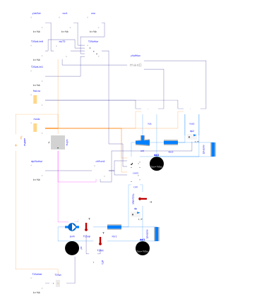
Extends from Buildings.Fluid.HydronicConfigurations.ActiveNetworks.Examples.BaseClasses.PartialDecoupling (Partial model of primary variable circuit serving a decoupling circuit).
Information
This model represents a cooling system where the configuration Buildings.Fluid.HydronicConfigurations.ActiveNetworks.Decoupling is used in conjunction with Buildings.Fluid.HydronicConfigurations.PassiveNetworks.SingleMixing. The combined configuration serves as the interface between a variable flow primary circuit and a variable flow consumer circuit. The primary circuit has a constant supply temperature. The consumer circuit has a varying supply temperature set point that is reset based on the terminal valve opening, with the most open valve being kept 90% open.
Note the following settings.
-
con1.dp1_nominal=con.dpBal3_nominalwhich is used to size the control valve and the pump of the mixing configuration, and avoids a reverse flow in the bypass at partial load due to the opposing differential pressure created by the decoupling configuration. See Buildings.Fluid.HydronicConfigurations.PassiveNetworks.Examples.SingleMixingOpenLoop for further details on that behavior. -
The controller
resT2that is used to reset the secondary supply temperature usesy_reset=1which yields the design supply temperature at the time when the controller is enabled. Otherwise there is a significant delay in satisfying the load, followed by a large overshoot, and the control loop is hard to tune.
The fact that the load seems unmet at partial load (see plot #4) is due to the load model that does not guarantee a linear variation of the load with the input signal in cooling mode, see Buildings.Fluid.HydronicConfigurations.ActiveNetworks.Examples.BaseClasses.Load.
Parameters
| Type | Name | Default | Description |
|---|---|---|---|
| Buildings.Fluid.HydronicConfigurations.Types.Control | typ (from PartialActivePrimary) | Buildings.Fluid.HydronicConfigurations.Types.Control.Heating | Load type |
| Integer | nTer (from PartialActivePrimary) | 2 | Number of terminal units |
| Real | kSizPum (from PartialActivePrimary) | 1.0 | Pump oversizing coefficient |
| Modelica.Units.SI.Pressure | p_min (from PartialActivePrimary) | 200000 | Circuit minimum pressure |
| Modelica.Units.SI.Temperature | TLiqEnt_nominal (from PartialActivePrimary) | if typ == Buildings.Fluid.HydronicConfigurations.Types.Control.Heating then 60 + 273.15 else 7 + 273.15 | Liquid entering temperature at design conditions |
| Modelica.Units.SI.Temperature | TLiqLvg_nominal (from PartialActivePrimary) | TLiqEnt_nominal + (if typ == Buildings.Fluid.HydronicConfigurations.Types.Control.Heating then -10 else +5) | Liquid leaving temperature at design conditions |
| Modelica.Units.SI.Temperature | TLiqEntChg_nominal (from PartialActivePrimary) | 60 + 273.15 | Liquid entering temperature in change-over mode |
| Modelica.Units.SI.Temperature | TLiqSup_nominal (from PartialActivePrimary) | TLiqEnt_nominal | Liquid primary supply temperature at design conditions |
| Modelica.Units.SI.Temperature | TLiqSupChg_nominal (from PartialActivePrimary) | TLiqEntChg_nominal | Liquid primary supply temperature in change-over mode |
| Modelica.Units.SI.PressureDifference | dp1_nominal (from PartialDecoupling) | dpPum_nominal - dpPip_nominal | Control valve pressure drop at design conditions |
| Nominal condition | |||
| Modelica.Units.SI.MassFlowRate | mTer_flow_nominal (from PartialActivePrimary) | 1 | Terminal unit mass flow rate at design conditions |
| Modelica.Units.SI.MassFlowRate | m1_flow_nominal (from PartialActivePrimary) | m2_flow_nominal | Mass flow rate in primary branch at design conditions |
| Modelica.Units.SI.MassFlowRate | m2_flow_nominal (from PartialActivePrimary) | nTer*mTer_flow_nominal | Mass flow rate in consumer circuit at design conditions |
| Modelica.Units.SI.PressureDifference | dpTer_nominal (from PartialActivePrimary) | 3E4 | Terminal unit pressure drop at design conditions |
| Modelica.Units.SI.PressureDifference | dpPip_nominal (from PartialActivePrimary) | 0.5E4 | Pipe section pressure drop at design conditions |
| Modelica.Units.SI.PressureDifference | dpPum_nominal (from PartialActivePrimary) | Pump head at design conditions | |
| Modelica.Units.SI.MassFlowRate | mPum_flow_nominal (from PartialActivePrimary) | m1_flow_nominal | Primary pump mass flow rate at design conditions |
| Modelica.Units.SI.PressureDifference | dp2_nominal (from PartialDecoupling) | dpPip_nominal + dp2Set | Consumer circuit pressure differential at design conditions |
| Dynamics › Conservation equations | |||
| Modelica.Fluid.Types.Dynamics | energyDynamics (from PartialActivePrimary) | Modelica.Fluid.Types.Dynamics.FixedInitial | Type of energy balance: dynamic (3 initialization options) or steady state |
| Configuration | |||
| Boolean | is_bal (from PartialDecoupling) | true | Set to true for balanced primary branch |
| Controls | |||
| Modelica.Units.SI.PressureDifference | dp2Set (from PartialDecoupling) | loa1.dpTer_nominal + loa1.dpValve_nominal | Consumer circuit pressure differential set point |
Components
Revisions
-
June 30, 2022, by Antoine Gautier:
First implementation.