
modelInjectionTwoWayVariable
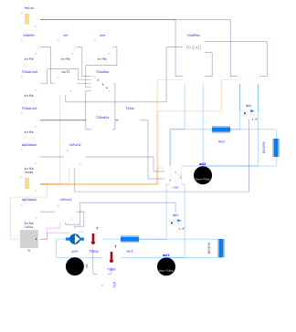
Extends from InjectionTwoWayConstantReturn.
Information
This model is almost similar to Buildings.Fluid.HydronicConfigurations.ActiveNetworks.Examples.InjectionTwoWayConstant except that a cooling system is represented, and the consumer circuit is a variable flow circuit with a variable speed pump and two-way valves. The pump speed is modulated to track a constant pressure differential at the boundaries of the remote terminal unit.
For this circuit to operate as intended, it is critical that the
secondary supply temperature set point be different from the primary
supply temperature.
Otherwise, the tracking error does not change sign and there is no
overshoot that can desaturate the integral term of the PI controller.
In other words, the controller output is fixed as soon as the measured
value equals the set point.
Therefore, the equilibrium point typically differs from the control
intent which is a primary flow rate varying with the load.
One can observe that behavior by setting
TLiqSup_nominal=TLiqEnt_nominal and
have_resT2=false.
Such setting yields a fixed valve position with a primary recirculation
and a flow reversal in the bypass whereas the control intent would
be a slightly closer position ensuring a positive flow in the bypass.
Note that this is nearly invisible from an operating standpoint
since the set point and the loads are met.
However, this is definitely detrimental to the overall performance
as the primary circuit is operated at a higher flow rate and lower
ΔT than needed.
The system practically behaves as there was no control valve installed
on the primary return line.
The fact that the load seems unmet at partial load (see plot #4) is due to the load model that does not guarantee a linear variation of the load with the input signal in cooling mode, see Buildings.Fluid.HydronicConfigurations.ActiveNetworks.Examples.BaseClasses.Load.
Parameters
| Type | Name | Default | Description |
|---|---|---|---|
| Buildings.Fluid.HydronicConfigurations.Types.Control | typ (from PartialActivePrimary) | Buildings.Fluid.HydronicConfigurations.Types.Control.Heating | Load type |
| Integer | nTer (from PartialActivePrimary) | 2 | Number of terminal units |
| Real | kSizPum (from PartialActivePrimary) | 1.0 | Pump oversizing coefficient |
| Modelica.Units.SI.Pressure | p_min (from PartialActivePrimary) | 200000 | Circuit minimum pressure |
| Modelica.Units.SI.Temperature | TLiqEnt_nominal (from PartialActivePrimary) | if typ == Buildings.Fluid.HydronicConfigurations.Types.Control.Heating then 60 + 273.15 else 7 + 273.15 | Liquid entering temperature at design conditions |
| Modelica.Units.SI.Temperature | TLiqLvg_nominal (from PartialActivePrimary) | TLiqEnt_nominal + (if typ == Buildings.Fluid.HydronicConfigurations.Types.Control.Heating then -10 else +5) | Liquid leaving temperature at design conditions |
| Modelica.Units.SI.Temperature | TLiqEntChg_nominal (from PartialActivePrimary) | 60 + 273.15 | Liquid entering temperature in change-over mode |
| Modelica.Units.SI.Temperature | TLiqSup_nominal (from PartialActivePrimary) | TLiqEnt_nominal | Liquid primary supply temperature at design conditions |
| Modelica.Units.SI.Temperature | TLiqSupChg_nominal (from PartialActivePrimary) | TLiqEntChg_nominal | Liquid primary supply temperature in change-over mode |
| Nominal condition | |||
| Modelica.Units.SI.MassFlowRate | mTer_flow_nominal (from PartialActivePrimary) | 1 | Terminal unit mass flow rate at design conditions |
| Modelica.Units.SI.MassFlowRate | m1_flow_nominal (from PartialActivePrimary) | m2_flow_nominal | Mass flow rate in primary branch at design conditions |
| Modelica.Units.SI.MassFlowRate | m2_flow_nominal (from PartialActivePrimary) | nTer*mTer_flow_nominal | Mass flow rate in consumer circuit at design conditions |
| Modelica.Units.SI.PressureDifference | dpTer_nominal (from PartialActivePrimary) | 3E4 | Terminal unit pressure drop at design conditions |
| Modelica.Units.SI.PressureDifference | dpPip_nominal (from PartialActivePrimary) | 0.5E4 | Pipe section pressure drop at design conditions |
| Modelica.Units.SI.PressureDifference | dpPum_nominal (from PartialActivePrimary) | Pump head at design conditions | |
| Modelica.Units.SI.MassFlowRate | mPum_flow_nominal (from PartialActivePrimary) | m1_flow_nominal | Primary pump mass flow rate at design conditions |
| Modelica.Units.SI.PressureDifference | dp2_nominal (from PartialInjectionTwoWay) | Consumer circuit pressure differential at design conditions | |
| Modelica.Units.SI.Temperature | T2Set_nominal (from InjectionTwoWayConstant) | if con.typVar == Buildings.Fluid.HydronicConfigurations.Types.ControlVariable.SupplyTemperature then TLiqEnt_nominal else TLiqLvg_nominal | Consumer circuit design temperature set point |
| Modelica.Units.SI.Temperature | TAirEnt_nominal (from InjectionTwoWayConstant) | 293.15 | Air entering temperature at design conditions |
| Modelica.Units.SI.MassFraction | phiAirEnt_nominal (from InjectionTwoWayConstant) | 0.5 | Air entering relative humidity at design conditions |
| Modelica.Units.SI.MassFlowRate | mAir_flow_nominal (from InjectionTwoWayConstantReturn) | 6.8 | Air mass flow rate at design conditions |
| Dynamics › Conservation equations | |||
| Modelica.Fluid.Types.Dynamics | energyDynamics (from PartialActivePrimary) | Modelica.Fluid.Types.Dynamics.FixedInitial | Type of energy balance: dynamic (3 initialization options) or steady state |
| Configuration | |||
| Boolean | is_bal (from PartialInjectionTwoWay) | false | Set to true for balanced primary branch |
| Boolean | have_resT2 (from InjectionTwoWayConstant) | false | Set to true for consumer circuit temperature reset, false for constant set point |
| Controls | |||
| Modelica.Units.SI.PressureDifference | dp1Set (from PartialInjectionTwoWay) | 1e4 | Pressure differential set point |
| Modelica.Units.SI.PressureDifference | dp2Set | loa1.dpTer_nominal + loa1.dpValve_nominal | Secondary pressure differential set point |
Components
Revisions
-
June 30, 2022, by Antoine Gautier:
First implementation.