modelSideCold
Control block for cold side
Information
This block serves as the controller for the cold side of the ETS in Buildings.Obsolete.DHC.ETS.Combined.Controls.Supervisory. It computes the following control signals.
-
Control signals for ambient sources
yAmb(array)
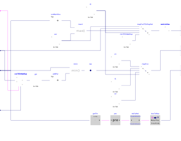
The cold rejection control signal yielded by the hot side controller is processed as follows.-
A controller is used to track the chilled water
supply temperature (CHWST) set point.
This controller is enabled when cooling is enabled.
It yields a control signal value between
0andnSouAmb. -
The systems serving as ambient sources are then controlled in sequence
by mapping the minimum between the CHWST control loop output and the
part of the cold rejection signal between
0andnSouAmbto anSouAmb-array of signals between0and1.
-
A controller is used to track the chilled water
supply temperature (CHWST) set point.
This controller is enabled when cooling is enabled.
It yields a control signal value between
-
Chilled water supply temperature set point
TChiWatSupSet
The remaining part of the cold rejection signal betweennSouAmbandnSouAmb+1is used to reset the CHWST set point between a maximum value provided as an input variable, and a minimum value provided as a parameter. -
Control signal for the evaporator loop isolation valve
yIsoAmb
The valve is commanded to be fully open whenever the cold rejection control signal is greater than zero. The command signal is held for 5 min to avoid short cycling.
Parameters
| Type | Name | Default | Description |
|---|---|---|---|
| Integer | nSouAmb | 1 | Number of ambient sources to control |
| Real | TChiWatSupSetMin | Minimum value of chilled water supply temperature set point | |
| Buildings.Controls.OBC.CDL.Types.SimpleController | controllerType | Buildings.Controls.OBC.CDL.Types.SimpleController.PI | Type of controller |
| Real | k | 0.1 | Gain of controller |
| Real | Ti | 120 | Time constant of integrator block |
Connectors
| Type | Name | Default | Description |
|---|---|---|---|
| Buildings.Controls.OBC.CDL.Interfaces.BooleanInput | uHeaCoo | Enable signal for heating or cooling | |
| Buildings.Controls.OBC.CDL.Interfaces.RealInput | TSet | Supply temperature set point (heating or chilled water) | |
| Buildings.Controls.OBC.CDL.Interfaces.RealInput | uCol | Cold rejection control signal | |
| Buildings.Controls.OBC.CDL.Interfaces.RealInput | TBot | Temperature at bottom of tank | |
| Buildings.Controls.OBC.CDL.Interfaces.RealOutput | TChiWatSupSet | Chilled water supply temperature set point | |
| Buildings.Controls.OBC.CDL.Interfaces.RealOutput[nSouAmb] | yAmb | Control signal for ambient sources | |
| Buildings.Controls.OBC.CDL.Interfaces.RealOutput | yValIso | Ambient loop isolation valve control signal |
Components
Revisions
-
March 7, 2025, by Michael Wetter:
Increased, and added where missing, hysteresis, as the input signal is the output of the PID controller. -
November 22, 2024, by Michael Wetter:
Reduced number of time events by replacing zero order hold with true and false hold, and increasing the minimum cycle time.
This is for #4058. -
July 31, 2020, by Antoine Gautier:
First implementation.