
modelAirToWater
Extends from Modelica.Icons.Example (Icon for runnable examples).
Information
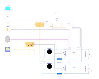
This model validates Buildings.Templates.Plants.HeatPumps.AirToWater by simulating a 24-hour period with overlapping heating and cooling loads. The heating loads reach their peak value first, the cooling loads reach it last.
Three equally sized heat pumps are modeled, which can all be lead/lag alternated.
A heat recovery chiller is included (pla.have_hrc_select=true)
and connected to the HW and CHW return pipes (sidestream integration).
A unique aggregated load is modeled on each loop using a heat exchanger component
exposed to conditioned space air, and a two-way modulating valve.
An importance multiplier of 10 is applied to the plant requests
and reset requests generated from the valve position.
The user can toggle the top-level parameter have_chiWat
to switch between a cooling and heating system (the default setting)
to a heating-only system.
Advanced equipment and control options can be modified via the parameter
dialog of the plant component.
Simulating this model shows how the plant responds to a varying load by
- staging or unstaging the AWHPs and the HRC with the associated primary pumps,
- rotating lead/lag alternate equipment to ensure even wear,
- resetting the supply temperature and remote differential pressure in both the CHW and HW loops based on the valve position,
- staging and controlling the secondary pumps to meet the remote differential pressure setpoint.
Note that the HRC model does not explicitly represent compressor cycling. As a result, the cycling-based disabling condition specified in Buildings.Templates.Plants.Controls.HeatRecoveryChillers.Enable is never triggered. This limitation may lead to overestimating the HRC operating time.
Details
By default, all valves within the plant are modeled considering a linear
variation of the pressure drop with the flow rate (pla.linearized=true),
as opposed to the quadratic relationship usually considered for
a turbulent flow regime.
By limiting the size of the system of nonlinear equations, this setting
reduces the risk of solver failure and the time to solution for testing
various plant configurations.
Parameters
| Type | Name | Default | Description |
|---|---|---|---|
| UserProject.Data.AllSystems | datAll | Plant parameters | |
| Modelica.Units.SI.PressureDifference | dpTer_nominal | 3E4 | Liquid pressure drop across terminal unit at design conditions |
| Modelica.Units.SI.PressureDifference | dpValve_nominal | dpTer_nominal | Terminal unit control valve pressure drop at design conditions |
| Configuration | |||
| Boolean | have_chiWat | true | Set to true if the plant provides CHW |
| Assumptions | |||
| Boolean | allowFlowReversal | true | = true to allow flow reversal, false restricts to design direction (port_a -> port_b) |
| Dynamics › Conservation equations | |||
| Modelica.Fluid.Types.Dynamics | energyDynamics | Modelica.Fluid.Types.Dynamics.FixedInitial | Type of energy balance: dynamic (3 initialization options) or steady state |
Connectors
| Type | Name | Default | Description |
|---|---|---|---|
| AirHandlersFans.Interfaces.Bus | busAirHan | AHU control bus | |
| Interfaces.Bus | busPla | Plant control bus |
Components
Contents
| Name | Description |
|---|---|
 Medium Medium |
Revisions
-
December 2, 2025, by Antoine Gautier:
Updated load model.
This is for #4432. -
August 21, 2025, by Antoine Gautier:
Refactored with load-dependent 2D table data heat pump model.
This is for #4152. -
May 31, 2024, by Antoine Gautier:
Added sidestream HRC and refactored the model after updating the HP plant template. This is for #3808. -
March 29, 2024, by Antoine Gautier:
First implementation.