
modelMixedConvection
Extends from Modelica.Icons.Example (Icon for runnable examples).
Information
This tutorial gives step by step instructions on building and simulating a mixed convection model. The model tests the coupled simulation of Buildings.ThermalZones.Detailed.CFD with the FFD program by simulating ventilation with mixed convection in an empty room.
Case Description
The temperature of the floor is fixed at 30°C and the temperature of the walls and the ceiling are fixed at 10°C. The supply air temperature is fixed at 10°C.
Figure (a) shows the schematic of the FFD simulation and Figure (b) shows the velocity vectors and temperatures on the X-Z plane at Y = 0.5 m as simulated by the FFD.
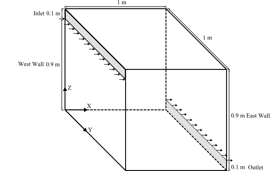
Figure (a)
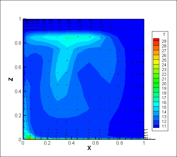
Figure (b)
Step by Step Guide
This section describes step by step how to build and simulate the model.
-
Add the following model components into the
MixedConvectionmodel:-
Buildings.ThermalZones.Detailed.CFD.
This model is used to implement data exchange between Modelica and FFD.
Name it as
roo. -
Buildings.BoundaryConditions.WeatherData.ReaderTMY3.
Use weather data from OHare Intl. Airport, Chicago, Illinoi, U.S.A.
Name it as
weaDat. -
Modelica.Blocks.Sources.Constant.
Three models are needed to specify that internal radiation, internal convective heat gain and internal latent heat gain are zero.
Name these models as
qRadGai_flow,qConGai_flowandqLatGai_flow, respectively. -
Modelica.Blocks.Routing.Multiplex3.
This block is used to convert three numbers into a vector.
Name it as
multiple_x3. -
Buildings.HeatTransfer.Sources.FixedTemperature.
Two models are needed to specify the temperature on the floor and other walls.
Name them as
TFloandTOthWalrespectively. Please note that it is necessary to declareTOthWalas a vector of 5 elements. -
Buildings.Fluid.Sources.MassFlowSource_T.
This model provides inlet air for the
roo. Name it asbouIn. -
Buildings.Fluid.Sources.Boundary_pT.
This model is the outdoor environment to which the outlet of
roois connected. Name it asbouOut.
-
Buildings.ThermalZones.Detailed.CFD.
This model is used to implement data exchange between Modelica and FFD.
Name it as
-
In the textual editor mode, add the medium and the number of surfaces as below:
package MediumA = Buildings.Media.GasesConstantDensity.MoistAirUnsaturated (T_default=283.15);
  parameter Integer nConExtWin=0;
  parameter Integer nConBou=0;
  parameter Integer nSurBou=6;
  parameter Integer nConExt=0;
  parameter Integer nConPar=0;
-
Edit
rooas below:Buildings.ThermalZones.Detailed.CFD roo( redeclare package Medium = MediumA, surBou( name={"East Wall","West Wall","North Wall","South Wall","Ceiling","Floor"}, A={0.9,0.9,1,1,1,1}, til={Buildings.Types.Tilt.Wall, Buildings.Types.Tilt.Wall, Buildings.Types.Tilt.Wall, Buildings.Types.Tilt.Wall, Buildings.Types.Tilt.Ceiling, Buildings.Types.Tilt.Floor}, each absIR=1e-5, each absSol=1e-5, each boundaryCondition=Buildings.ThermalZones.Detailed.Types.CFDBoundaryConditions.Temperature), AFlo = 1*1, hRoo = 1, linearizeRadiation = false, useCFD = true, sensorName = {"Occupied zone air temperature", "Velocity"}, cfdFilNam = "resources/Buildings/Resources/Data/ThermalZones/Detailed/Examples/FFD/Tutorial/MixedConvection.ffd", nConExt = nConExt, nConExtWin = nConExtWin, nConPar = nConPar, nConBou = nConBou, nSurBou = nSurBou, nPorts = 2, portName={"Inlet","Outlet"}, samplePeriod = 6); -
Set the parameters for the following components:
-
Set
qRadGai_flow,qConGai_flowandqLatGai_flowto 0. -
Set
TFloto 303.15 Kelvin. -
Set
TOthWalto 283.15 Kelvin.
-
Set
-
Set the values for the parameters of
bouInandbouOutas below:Fluid.Sources.MassFlowSource_T bouIn( redeclare package Medium = MediumA, nPorts=1, m_flow=0.1, T=283.15);
Fluid.Sources.FixedBoundary bouOut(
  redeclare package Medium = MediumA,
  nPorts=1);
-
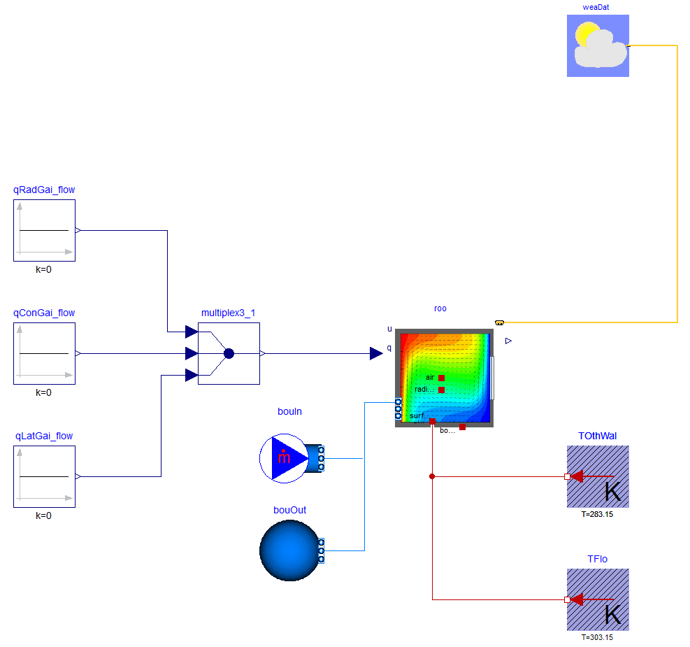
Connect the components as shown in the figure below.
-
Confirm in the textual editor that the connections to
roo.portsare as follows:connect(bouIn.ports[1], roo.ports[1]); connect(bouOut.ports[1], roo.ports[2]);
-
Use the Simplified CFD Interface (SCI) to generate the input file for the FFD.
- Use a 20 X 20 X 20 stretched grid.
- Set the time step size of the FFD to 0.1 seconds.
-
Generate the input files, which have by default the names
input.cfd(mesh file) andzeroone.dat(obstacles file). -
Rename the files as
MixedConvection.cfdandMixedConvection.dat, respectively.
-
Revise the FFD parameter input file
MixedConvection.ffd(an example file is available inBuildings/Resources/Data/ThermalZones/Detailed/Examples/FFD/Tutorial/):inpu.parameter_file_format SCI inpu.parameter_file_name MixedConvection.cfd inpu.block_file_name MixedConvection.dat prob.nu 0.000015 // Kinematic viscosity prob.rho 1.205 // Density prob.gravx 0 // Gravity in x direction prob.gravy 0 // Gravity in y direction prob.gravz -9.81 // Gravity in z direction prob.cond 0.0257 // Conductivity prob.Cp 1006.0 // Specific heat capacity prob.beta 0.00343 // Thermal expansion coefficient prob.diff 0.00001 // Diffusivity for contaminants prob.coeff_h 0.0004 // Convective heat transfer coefficient near the wall prob.Temp_Buoyancy 10.0 // Reference temperature for calculating buoyance force init.T 10.0 // Initial condition for Temperature init.u 0.0 // Initial condition for velocity u init.v 0.0 // Initial condition for velocity v init.w 0.0 // Initial condition for velocity w
-
Put the files
MixedConvection.ffd,MixedConvection.dat, andMixedConvection.cfdin the directoryBuildings/Resources/Data/ThermalZones/Detailed/Examples/FFD/Tutorial/. -
Set the simulation stop time of the Modelica model to
180seconds and choose, for example, the CVode solver. - Translate the model and start the simulation.
-
Post-process: click the Tecplot macro script
Buildings/Resources/Image/Rooms/Examples/FFD/Tutorial/MixedConvection.mcrthat will generate the temperature contour and velocity vectors shown in the Figure (b). Note: Tecplot is needed for this.
Parameters
| Type | Name | Default | Description |
|---|---|---|---|
| Integer | nConExtWin | 0 | Number of constructions with a window |
| Integer | nConBou | 0 | Number of surface that are connected to constructions that are modeled inside the room |
| Integer | nSurBou | 6 | Number of surface that are connected to the room air volume |
| Integer | nConExt | 0 | Number of exterior constructions withour a window |
| Integer | nConPar | 0 | Number of partition constructions |
Components
| Type | Name | Default | Description |
|---|---|---|---|
| Modelica.Blocks.Sources.Constant | qRadGai_flow | Radiative heat gain | |
| Modelica.Blocks.Sources.Constant | qConGai_flow | Convective heat gain | |
| Modelica.Blocks.Sources.Constant | qLatGai_flow | Latent heat gain | |
| Modelica.Blocks.Routing.Multiplex3 | multiplex3_1 | ||
| BoundaryConditions.WeatherData.ReaderTMY3 | weaDat | ||
| Buildings.ThermalZones.Detailed.CFD | roo | ||
| HeatTransfer.Sources.FixedTemperature[nSurBou - 1] | TOthWal | Temperature for other walls | |
| HeatTransfer.Sources.FixedTemperature | TFlo | Temperature of floor | |
| Fluid.Sources.MassFlowSource_T | bouIn | Mass flow boundary condition | |
| Buildings.Fluid.Sources.Boundary_pT | bouOut | Pressure boundary condition |
Contents
| Name | Description |
|---|---|
 MediumA MediumA | Medium model |
Revisions
-
September 16, 2021, by Michael Wetter:
Removed assignment of parameterlatas this is now obtained from the weather data reader.
This is for IBPSA, #1477. -
September 07, 2017, by Thierry Nouidui:
Refactored the FFD C-code and revised the documentation. This is for issue 612. -
July 25, 2014, by Michael Wetter:
Revised documentation. -
June 27, 2014, by Wei Tian, Thomas Sevilla, Wangda Zuo:
First implementation.