
modelNaturalConvection
Extends from Modelica.Icons.Example (Icon for runnable examples).
Information
This tutorial gives step by step instructions for building and simulating a natural convection model. The model tests the coupled simulation of Buildings.ThermalZones.Detailed.CFD with the FFD program by simulating the natural convection in an empty room with only surface boundary conditions.
Case Description
The Rayleigh number is a dimensionless number associated with natural convection, defined as
Ra = g β (Tw-Te)L3 ⁄ (ν α)
To get a Rayleigh number of 1E5, the flow properties are manually set as acceleration due to gravity gz=-0.01 m/s2, thermal expansion coefficient β=3e-3 K-1, kinematic viscosity ν=1.5e-5 m2/s, thermal diffusivity α=2e-5 m2/s, and characteristic length L=1 m.
Figure (a) shows the schematic of the FFD simulation. The following conditions are applied in Modelica.:
- East wall: Fixed temperature at Te=0°C,
- West wall: Fixed temperature at Tw=1°C,
- North & South wall, Ceiling, Floor: Fixed heat flux at 0 W/m2.
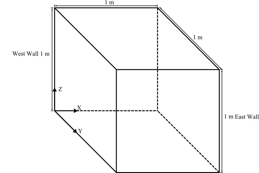
Figure (a)
Figure (b) shows the velocity vectors and temperature contour in degree Celsius on the X-Z plane at Y = 0.5 m as simulated by the FFD.
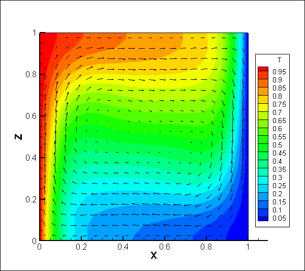
Figure (b)
More details of the case description can be found in Zuo et al. (2012).
Step by Step Guide
This section describes step by step how to build and simulate the model.
-
Add the following component models to the
NaturalConvectionmodel:-
Buildings.ThermalZones.Detailed.CFD.
This model is used to implement the data exchange between Modelica and FFD. Name it as
roo. -
Buildings.BoundaryConditions.WeatherData.ReaderTMY3.
Use weather data from OHare Intl. Airport, Chicago, Illinoi, U.S.A. Name it as
weaDat. -
Modelica.Blocks.Sources.Constant.
Three models are needed to specify that internal radiation, internal convective heat gain and internal latent heat gain zero.
Name these models as
qRadGai_flow,qConGai_flowandqLatGai_flow, respectively. -
Modelica.Blocks.Routing.Multiplex3.
This block is used to combine three scalar signals to a vector. Name it as
multiple_x3. -
Buildings.HeatTransfer.Sources.FixedTemperature.
Two models are needed to specify the temperatures on the east and west walls.
Name them as
TeasWalandTwesWal, respectively.
-
Buildings.ThermalZones.Detailed.CFD.
This model is used to implement the data exchange between Modelica and FFD. Name it as
-
In the textual editor mode, add the medium and the number of surfaces as shown below:
Buildings.ThermalZones.Detailed.CFD roo( package MediumA = Buildings.Media.GasesConstantDensity.MoistAirUnsaturated( T_default=283.15); parameter Integer nConExtWin=0; parameter Integer nConBou=0; parameter Integer nSurBou=6; parameter Integer nConExt=0; parameter Integer nConPar=0; -
Edit
rooas below:edeclare package Medium = MediumA, surBou( name={"East Wall","West Wall","North Wall","South Wall","Ceiling","Floor"}, each A=1*1, til={Buildings.Types.Tilt.Wall, Buildings.Types.Tilt.Wall, Buildings.Types.Tilt.Wall, Buildings.Types.Tilt.Wall, Buildings.Types.Tilt.Ceiling, Buildings.Types.Tilt.Floor}, each absIR=1e-5, each absSol=1e-5, boundaryCondition={ Buildings.ThermalZones.Detailed.Types.CFDBoundaryConditions.Temperature, Buildings.ThermalZones.Detailed.Types.CFDBoundaryConditions.Temperature, Buildings.ThermalZones.Detailed.Types.CFDBoundaryConditions.HeatFlowRate, Buildings.ThermalZones.Detailed.Types.CFDBoundaryConditions.HeatFlowRate, Buildings.ThermalZones.Detailed.Types.CFDBoundaryConditions.HeatFlowRate, Buildings.ThermalZones.Detailed.Types.CFDBoundaryConditions.HeatFlowRate}), AFlo = 1*1, hRoo = 1, linearizeRadiation = false, useCFD = true, sensorName = {"Occupied zone air temperature", "Velocity"}, cfdFilNam = "resources/Buildings/Resources/Data/ThermalZones/Detailed/Examples/FFD/Tutorial/NaturalConvection.ffd", nConExt = nConExt, nConExtWin = nConExtWin, nConPar = nConPar, nConBou = nConBou, nSurBou = nSurBou, T_start=273.15, samplePeriod = 60); -
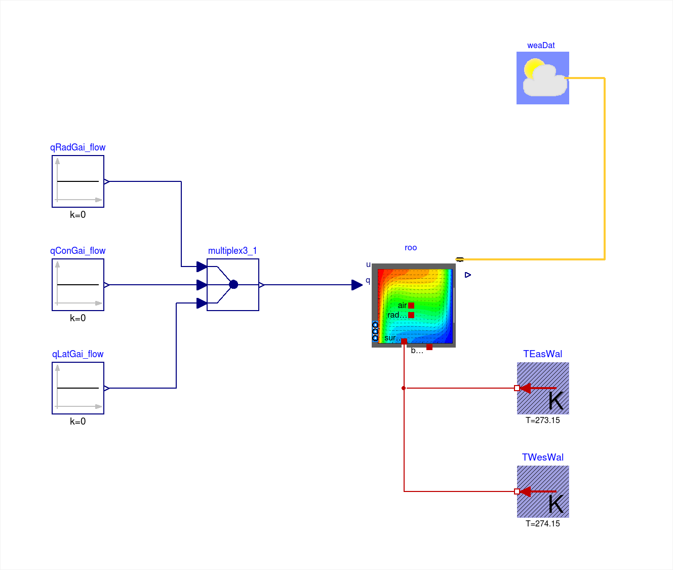
Connect the component as shown in the figure below.
-
Set the values for the following components:
-
Set
qRadGai_flow,qConGai_flowandqLatGai_flowto 0. -
Set
TEasWalto 273.15 Kelvin. -
Set
TWesWalto 274.15 Kelvin.
-
Set
-
Use the Simplified CFD Interface (SCI) to generate the input file for FFD.
- Use a 20 x 20 x 20 uniform grid.
- Set the time step size of the FFD to 10 seconds.
-
Generate the input files which have the default names
input.cfd(mesh file) andzeroone.dat(obstacles file). -
Rename the files as
NaturalConvection.cfdandNaturalConvection.dat, respectively.
-
Revise the FFD parameter input file
NaturalConvection.ffd(an example file is provided inBuildings/Resources/Data/ThermalZones/Detailed/Examples/FFD/Tutorial/):inpu.parameter_file_format SCI inpu.parameter_file_name NaturalConvection.cfd inpu.block_file_name NaturalConvection.dat prob.nu 1.5e-5 // Kinematic viscosity prob.rho 1 // Density prob.gravx 0 // Gravity in x direction prob.gravy 0 // Gravity in y direction prob.gravz -0.01 // Gravity in z direction prob.cond 0.02 // Conductivity prob.Cp 1000.0 // Specific heat capacity prob.beta 3e-3 // Thermal expansion coefficient prob.diff 0.00001 // Diffusivity for contaminants prob.alpha 2e-5 // Thermal diffusivity prob.coeff_h 0.0004 // Convective heat transfer coefficient near the wall prob.Temp_Buoyancy 0.0 // Reference temperature for calculating buoyance force init.T 0.0 // Initial condition for Temperature init.u 0.0 // Initial condition for velocity u init.v 0.0 // Initial condition for velocity v init.w 0.0 // Initial condition for velocity w
Please note that some of the physical properties were manipulated to obtain the desired Rayleigh Number of 105.
-
Store
NaturalConvection.ffd,NaturalConvection.dat, andNaturalConvection.cfdatBuildings/Resources/Data/ThermalZones/Detailed/Examples/FFD/Tutorial. -
Set simulation the stop time of the Modelica model
3600seconds and choose for example the CVode solver. - Translate the model and start the simulation.
-
Post-process: click the Tecplot macro script
Buildings/Resources/Image/Rooms/Examples/FFD/Tutorial/NaturalConvection.mcrthat will generate the temperature contour and velocity vectors shown in the Figure (b). Note: Tecplot is needed for this.
Parameters
| Type | Name | Default | Description |
|---|---|---|---|
| Integer | nConExtWin | 0 | Number of constructions with a window |
| Integer | nConBou | 0 | Number of surface that are connected to constructions that are modeled inside the room |
| Integer | nSurBou | 6 | Number of surface that are connected to the room air volume |
| Integer | nConExt | 0 | Number of exterior constructions withour a window |
| Integer | nConPar | 0 | Number of partition constructions |
Components
| Type | Name | Default | Description |
|---|---|---|---|
| Modelica.Blocks.Sources.Constant | qRadGai_flow | Radiative heat gain | |
| Modelica.Blocks.Sources.Constant | qConGai_flow | Convective heat gain | |
| Modelica.Blocks.Sources.Constant | qLatGai_flow | Latent heat gain | |
| Modelica.Blocks.Routing.Multiplex3 | multiplex3_1 | ||
| BoundaryConditions.WeatherData.ReaderTMY3 | weaDat | ||
| Buildings.ThermalZones.Detailed.CFD | roo | ||
| HeatTransfer.Sources.FixedTemperature | TWesWal | Boundary condition for the west wall | |
| HeatTransfer.Sources.FixedTemperature | TEasWal | Temperature of east wall |
Contents
| Name | Description |
|---|---|
 MediumA MediumA | Medium model |
Revisions
-
September 16, 2021, by Michael Wetter:
Removed assignment of parameterlatas this is now obtained from the weather data reader.
This is for IBPSA, #1477. -
September 07, 2017, by Thierry Nouidui:
Refactored the FFD C-code and revised the documentation. This is for issue 612. -
July 7, 2015 by Michael Wetter:
Removed model for prescribed heat flow boundary condition as the value was zero and hence the model is not needed. This is for issue 439. -
July 25, 2014, by Michael Wetter:
Revised documentation. -
June 27, 2014, by Wei Tian, Thomas Sevilla, Wangda Zuo:
First implementation.
References
Wangda Zuo, Mingang Jin, Qingyan Chen, 2012.
Reduction of numerical viscosity in FFD model.
Journal of Engineering Applications of Computational Fluid Mechanics, 6(2), p. 234-247.