
modelX3AWithRadiantFloor
Extends from Modelica.Icons.Example (Icon for runnable examples).
Information
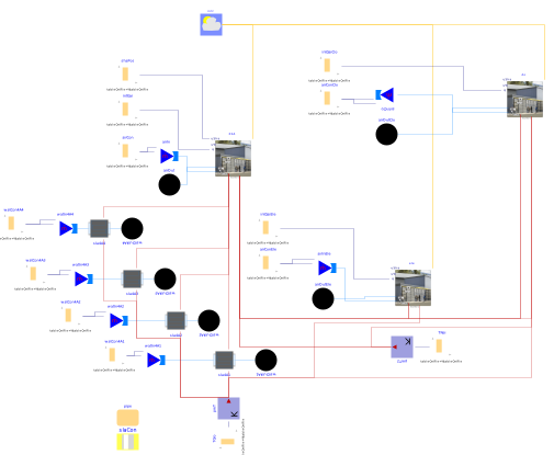
This model demonstrates one potential simulation using the models available in Buildings.ThermalZones.Detailed.FLEXLAB.Rooms.X3A. This example simulates test cell X3A when it is conditioned with a radiant slab. This example model includes heat transfer between the test cell, the outdoor environment, the radiant slab conditioning the test cell, the connected electrical room and closet, and the neighboring test cells.
The connections between the test cell and the external models are described in the following table. Only models not included in the X3A package are included. For documentation describing the connections between X3A models see Buildings.ThermalZones.Detailed.FLEXLAB.Rooms.X3A.
| External model name | External model significance | External model port | X3A port |
|---|---|---|---|
| weaDat | Outdoor weather | weaDat.weaBus | X3A.weaBus |
| TNei | Neighboring test cells (X2B and X3B) | X2B: X3A.preTem2.port[1] X3B: X3A.preTem2.port[2] |
X2B: X3A.surf_conBou[1] X3B: X3A.surf_conBou[2] |
| sla4A1 | Radiant slab serving the north portion of X3A | sla4A1.surf_a | X3A.surf_surBou[1] |
| sla4A2 | Radiant slab serving the north-central portion of X3A | sla4A2.surf_a | X3A.surf_surBou[2] |
| sla4A3 | Radiant slab serving the south-central portion of X3A | sla4A3.surf_a | X3A.surf_surBou[3] |
| sla4A4 | Radiant slab serving the south portion of X3A | sla4A4.surf_a | X3A.surf_surBou[4] |
| shaPos | Table describing the position of the window shade | shaPos.y[1] | X3A.uSha |
| intGai | Table specifying the internal gains in the space | intGai[1,2,3] | X3A.qGai_flow[1,2,3] |
| airIn | Prescribed airflow describing service air from the AHU | airIn.ports[1] | X3A.ports[1] |
| airOut | Outlet for ventilation air flow | airOut.ports[1] | X3A.ports[1] |
The connections between the closet and external models are described in the following table. Only connections to models not included in the X3A package are described.
| External model name | External model significance | External model port | clo port |
|---|---|---|---|
| intGaiClo | Table specifying the internal gains in the closet | intGaiClo[1,2,3] | clo.qGai_flow[1,2,3] |
| airInClo | Prescribed airflow describing service air from the AHU | airInClo.ports[1] | clo.ports[1] |
| airOutClo | Outlet for ventilation air flow | airOutClo.ports[1] | clo.ports[1] |
| preT | Prescribed temperature describing the ground temperature | preT.port | clo.surf_conBou[3] |
The connections between the electrical room and external models are described in the following table. Only connections to models not included in the X3A package are described.
| External model name | External model significance | External model port | ele port |
|---|---|---|---|
| intGaiEle | Table specifying the internal gains in the electrical room | intGaiEle[1,2,3] | ele.qGai_flow[1,2,3] |
| airInEle | Prescribed airflow describing service air from the AHU | airInEle.ports[1] | ele.ports[1] |
| airOutEle | Outlet for ventilation air flow | airOutEle.ports[1] | ele.ports[1] |
| preT | Prescribed temperature describing the ground temperature | preT.port | ele.surf_conBou[1] |
The radiant slab is modeled using an instance of Buildings.Fluid.HeatExchangers.RadiantSlabs.SingleCircuitSlab. All of the inputs used to define the radiant slab are taken from the architectural drawings. The following table describes the connections between models used in the radiant slab. The connection to X3A is not included because it was previously described.
| External model name | External model significance | External model port | Radiant slab port |
|---|---|---|---|
| watIn | Inlet for service fluid flow. Currently connects to a prescribed flow described in a table | watIn.ports[1] | sla.port_a |
| preT | Ground temperature beneath the radiant slab construction. Currently connects to a prescribed temperature defined in a table | preT.port | sla.surf_b |
| watOut | Outlet for service fluid flow | watOut.ports[1] | sla.port_b |
The model only simulates the space conditions, the effects of the radiant slab, and the
heat transfer between the rooms. The air handling unit, chilled water plant, shade control,
internal gains, and ground temperature are all modeled by reading data from tables.
Currently the ventilation air is read from an external data file, via the model
airCon, while the others use tables described in the data reader model. The table
below shows the name of data input files in the model, what physical phenomena the data file
describes, the physical quantity of each data file output, and the source of the data.
| Model name | Quantity described | Data source | y[1] significance | y[2] significance | y[3] significance | y[4] significance | |
|---|---|---|---|---|---|---|---|
| shaPos | Position of the shade | Table in model | Position of the shade | ||||
| intGai | Internal gains | Table in model | Radiant heat | Convective heat | Latent heat | ||
| airCon | Ventilation air from air handling unit | External text file | Mass flow rate | Temperature | |||
| watCon | Conditioning water from central plant | Table in model | Mass flow rate | Temperature | |||
| TGro | Ground temperature | Table in model | Temperature | ||||
| intGaiClo | Internal gains for the closet | Table in model | Radiant heat | Convective heat | Latent heat | ||
| intGaiEle | Internal gains for the electrical room | Table in model | Radiant heat | Convective heat | Latent heat | ||
| airConEle | Ventilation air from AHU in the electrical room | External text file | Mass flow rate | Temperature | |||
| airConClo | Ventilation air from AHU in closet | External text file | Mass flow rate | Temperature | |||
| TNei | Temperature of the neighboring cells | Table in model | X2B | X3B |
In the above table blank entries either show that there is no data to describe, or that the data is describing a quantity for a separate model. Two examples are:
- The table for shaPos only contains data for shade position. Because it only has a y[1] value the remaining columns in the table are left blank.
- airCon, airConClo, and airConEle all share an external data file. They all use the same temperature data, located in y[4] of the external data file. The three room models use different air mass flow rates. airCon uses the flow rate from y[1] in the data file, airConClo uses the flow rate from y[2], and airConEle uses the flow rate from y[3]. Thus, the other entries for each row in the table are left blank because the data is innapropriate for that particular model.
The ventilation air flow rates used during occupied hours in this example were calculated using the assumption of 4 air changes per hour (ACH). It is assumed that there is no ventilation flow during unoccupied hours.
Parameters
| Type | Name | Default | Description |
|---|---|---|---|
| Buildings.HeatTransfer.Data.OpaqueConstructions.Generic | slaCon | Construction of the slab | |
| Buildings.Fluid.Data.Pipes.PEX_RADTEST | pipe |
Components
| Type | Name | Default | Description |
|---|---|---|---|
| Buildings.ThermalZones.Detailed.FLEXLAB.Rooms.X3A.TestCell | X3A | ||
| Modelica.Blocks.Sources.CombiTimeTable | intGai | Internal gain heat flow (Radiant = 1, Convective = 2, Latent = 3) | |
| Modelica.Blocks.Sources.CombiTimeTable | shaPos | Position of the shade | |
| Modelica.Blocks.Sources.CombiTimeTable | airCon | Inlet air conditions (y[1] = m_flow, y[4] = T) | |
| Buildings.Fluid.Sources.MassFlowSource_T | airIn | Inlet air conditions (from AHU) for X3A | |
| Buildings.Fluid.Sources.Boundary_pT | airOut | Air outlet for X3A | |
| Buildings.Fluid.HeatExchangers.RadiantSlabs.SingleCircuitSlab | sla4A1 | Radiant slab serving the north side of cell X3A. Name is taken from drawing M3.02 | |
| Modelica.Blocks.Sources.CombiTimeTable | watCon4A1 | Inlet water conditions (y[1] = m_flow, y[2] = T) | |
| Buildings.Fluid.Sources.MassFlowSource_T | watIn4A1 | Inlet water conditions (from central plant) | |
| Buildings.Fluid.Sources.Boundary_pT | watOut4A1 | Water outlet | |
| Buildings.HeatTransfer.Sources.PrescribedTemperature | preT | Temperature of the ground | |
| Modelica.Blocks.Sources.CombiTimeTable | TGro | ||
| Buildings.BoundaryConditions.WeatherData.ReaderTMY3 | weaDat | ||
| Buildings.HeatTransfer.Sources.PrescribedTemperature[2] | preT2 | ||
| Buildings.ThermalZones.Detailed.FLEXLAB.Rooms.X3A.Electrical | ele | Model of the electrical room | |
| Buildings.ThermalZones.Detailed.FLEXLAB.Rooms.X3A.Closet | clo | Model of the closet | |
| Modelica.Blocks.Sources.CombiTimeTable | TNei | Temperature of the neighboring test cells (y[1] = X2B, y[2] = X3B) | |
| Modelica.Blocks.Sources.CombiTimeTable | intGaiEle | Internal gain heat flow for the electrical room | |
| Modelica.Blocks.Sources.CombiTimeTable | airConEle | Inlet air conditions for the connected electrical room (y[1] = m_flow, y[4] = T) | |
| Modelica.Blocks.Sources.CombiTimeTable | airConClo | Inlet air conditions for the connected closet (y[1] = m_flow, y[4] = T) | |
| Buildings.Fluid.Sources.MassFlowSource_T | airInEle | Inlet air conditions (from AHU) for the electrical room | |
| Buildings.Fluid.Sources.Boundary_pT | airOutEle | Air outlet from the electrical room | |
| Buildings.Fluid.Sources.MassFlowSource_T | airInClo | Inlet air conditions (from AHU) for the closet | |
| Buildings.Fluid.Sources.Boundary_pT | airOutClo | Air outlet from the closet | |
| Modelica.Blocks.Sources.CombiTimeTable | intGaiClo | Internal gain heat flow for the closet | |
| Modelica.Blocks.Sources.CombiTimeTable | watCon4A2 | Inlet water conditions (y[1] = m_flow, y[2] = T) | |
| Buildings.Fluid.Sources.MassFlowSource_T | watIn4A2 | Inlet water conditions (from central plant) | |
| Buildings.Fluid.HeatExchangers.RadiantSlabs.SingleCircuitSlab | sla4A2 | Radiant slab serving the north-central section of cell X3A. Name is taken from drawing M3.02 | |
| Buildings.Fluid.Sources.Boundary_pT | watOut4A2 | Water outlet | |
| Modelica.Blocks.Sources.CombiTimeTable | watCon4A3 | Inlet water conditions (y[1] = m_flow, y[2] = T) | |
| Buildings.Fluid.Sources.MassFlowSource_T | watIn4A3 | Inlet water conditions (from central plant) | |
| Buildings.Fluid.HeatExchangers.RadiantSlabs.SingleCircuitSlab | sla4A3 | Radiant slab serving the south-central section of cell X3A. Name is taken from drawing M3.02 | |
| Buildings.Fluid.Sources.Boundary_pT | watOut4A3 | Water outlet | |
| Modelica.Blocks.Sources.CombiTimeTable | watCon4A4 | Inlet water conditions (y[1] = m_flow, y[2] = T) | |
| Buildings.Fluid.Sources.MassFlowSource_T | watIn4A4 | Inlet water conditions (from central plant) | |
| Buildings.Fluid.HeatExchangers.RadiantSlabs.SingleCircuitSlab | sla4A4 | Radiant slab serving the south section of cell X3A. Name is taken from drawing M3.02 | |
| Buildings.Fluid.Sources.Boundary_pT | watOut4A4 | Water outlet |
Contents
| Name | Description |
|---|---|
 Air Air | Air model used in the example model |
 Water Water | Water model used in the radiant slab loop |
Revisions
-
January 09, 2017, by Thierry S. Nouidui:
Fixed wrongportindex. -
December 07, 2016, by Thierry S. Nouidui:
Changed example to place a state at the surface. -
April 21, 2016, by Michael Wetter:
ReplacedModelicaServices.ExternalReferences.loadResourcewithModelica.Utilities.Files.loadResource. -
December 22, 2014 by Michael Wetter:
RemovedModelica.Fluid.Systemto address issue #311. - September 2, 2014, by Michael Wetter:
Corrected wrong pipe diameter. - June 30, 2014, by Michael Wetter:
Specified equations to be used to compute the initial conditions. - October 11, 2013, by Michael Wetter:
Added missingparameterkeyword in the declaration of the data record. - Sep 16, 2013 by Peter Grant:
Added connections to include floor models in Closet and Electrical. - Jun 10, 2013 by Peter Grant:
First implementation.