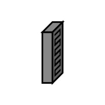
modelAnFP
Extends from Region (Base model for a 3D array of subregions).
Information
This model represents the anode flow plate of a PEMFC.
The x axis extends from the anode to the cathode. Fluid is considered to travel
in the y direction, with the associated length factor (ky) greater than one (by default)
to represent a serpentine channel.
The model is
bidirectional, meaning that either yNegative or yPositive can be
used as the inlet. By default, the cross-sectional area in the yz plane is 50 cm2.
The solid and the fluid phases are assumed to exist in the same subregions, even though a typical flow plate is impermeable to the fluid (except for the channel). In theory, it is possible to discretize the flow plate into smaller subregions for the bulk solid, lands, and valleys. However, this would significantly increase the mathematical size of the model. Currently, that level of detail is best left to computational fluid dynamics.
The x component of the transport factor (kx) for the gas and the liquid should generally be less than one because the transport distance into/out of the GDL is less that half the thickness of the flow plate. It is equal to the product of two ratios:
- the depth of the channels to the thickness of the flow plate
- the product of the total area of the flow plate in the yz plane (land + valleys) and the fraction of the total volume available for the fluid (ε) to the area of the valleys in the yz plane
See Species.'C+'.Graphite.Fixed
regarding the default specific heat capacity. The default thermal resistivity
of the carbon (θ = U.m*U.K/(95*U.W)) and the
electrical conductivity (σ = U.S/(1.470e-3*U.cm))
are that of Entegris/Poco Graphite AXF-5Q
[Entegris2012].
There is additional data in the
text layer of this model.
For more information, please see the Region model.
Parameters
| Type | Name | Default | Description |
|---|---|---|---|
| Integer | n_x (from Region) | size(L_x, 1) | Number of sets of subregions along the x axis |
| Integer | n_y (from Region) | size(L_y, 1) | Number of sets of subregions along the y axis |
| Integer | n_z (from Region) | size(L_z, 1) | Number of sets of subregions along the z axis |
| Q.Length[Axis] | L (from Region) | {sum(L_x), sum(L_y), sum(L_z)} | Length |
| Q.Area[Axis] | A (from Region) | {L[cartWrap(axis + 1)]*L[cartWrap(axis + 2)] for axis in Axis} | Cross-sectional areas |
| Q.Volume | V (from Region) | product(L) | Volume |
| Q.Length | D | 0.937*U.mm | Hydraulic diameter of the channel |
| Q.Length | L_channel | 162.4*U.cm | Length of the channel |
| Geometry | |||
| Q.Length[:] | L_x (from Region) | {U.cm} | Lengths along the x axis |
| Q.Length[:] | L_y (from Region) | {U.cm} | Lengths along the y axis |
| Q.Length[:] | L_z (from Region) | {U.cm} | Lengths across the z axis |
| Q.NumberAbsolute | epsilon | 0.0588 | Fraction of volume for the fluid |
| Assumptions › Included transport axes | |||
| Boolean | inclTransX (from Region) | true | X |
| Boolean | inclTransY (from Region) | true | Y |
| Boolean | inclTransZ (from Region) | true | Z |
Connectors
| Type | Name | Default | Description |
|---|---|---|---|
| Connectors.BoundaryBus[n_y,n_z] | xNegative (from Region) | Negative boundary along the x axis | |
| Connectors.BoundaryBus[n_y,n_z] | xPositive (from Region) | Positive boundary along the x axis | |
| Connectors.BoundaryBus[n_x,n_z] | yNegative (from Region) | Negative boundary along the y axis | |
| Connectors.BoundaryBus[n_x,n_z] | yPositive (from Region) | Positive boundary along the y axis | |
| Connectors.BoundaryBus[n_x,n_y] | zNegative (from Region) | Negative boundary along the z axis | |
| Connectors.BoundaryBus[n_x,n_y] | zPositive (from Region) | Positive boundary along the z axis |
Components
| Type | Name | Default | Description |
|---|---|---|---|
| Subregion[n_x,n_y,n_z] | subregions (from Region) | Instances of the subregion model |