
modelPump_Nrpm_stratos
Model validation using a Wilo Stratos 80/1-12 pump
Extends from Modelica.Icons.Example (Icon for runnable examples).
Information
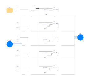
This example provides a validation for the Nrpm model. A Wilo Stratos 80/1-12 pump is simulated for five different RPMs for load that changes with time. The resulting curves for the pump head and mass flow rate are plotted using colored lines over the pump data sheet. The resulting figures are shown below.
Pump heads:

Pump electrical power:
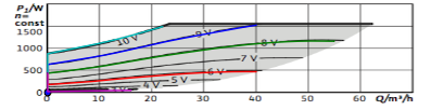
The figures are adapted from the Wilo Stratos 80/1-12 data sheet.
Parameters
| Type | Name | Default | Description |
|---|---|---|---|
| Data.Pumps.Wilo.Stratos80slash1to12 | per | Pump performance data |
Components
| Type | Name | Default | Description |
|---|---|---|---|
| IBPSA.Fluid.Sources.Boundary_pT | sou | Boundary condition with fixed pressure | |
| IBPSA.Fluid.Sources.Boundary_pT | sin | Boundary condition with fixed pressure | |
| Modelica.Blocks.Sources.Ramp | m_flow | Ramp signal for forced mass flow rate | |
| IBPSA.Fluid.Movers.SpeedControlled_Nrpm | pump1 | Wilo Stratos pump | |
| IBPSA.Fluid.Movers.SpeedControlled_Nrpm | pump2 | Wilo Stratos pump | |
| IBPSA.Fluid.Movers.SpeedControlled_Nrpm | pump3 | Wilo Stratos pump | |
| IBPSA.Fluid.Movers.SpeedControlled_Nrpm | pump4 | Wilo Stratos pump | |
| IBPSA.Fluid.Movers.SpeedControlled_Nrpm | pump5 | Wilo Stratos pump | |
| IBPSA.Fluid.Movers.FlowControlled_m_flow | forcedPump1 | Pump for forcing a certain mass flow rate | |
| IBPSA.Fluid.Movers.FlowControlled_m_flow | forcedPump2 | Pump for forcing a certain mass flow rate | |
| IBPSA.Fluid.Movers.FlowControlled_m_flow | forcedPump3 | Pump for forcing a certain mass flow rate | |
| IBPSA.Fluid.Movers.FlowControlled_m_flow | forcedPump4 | Pump for forcing a certain mass flow rate | |
| IBPSA.Fluid.Movers.FlowControlled_m_flow | forcedPump5 | Pump for forcing a certain mass flow rate | |
| Modelica.Blocks.Sources.Constant | rpm1 | Pump speed control signal | |
| Modelica.Blocks.Sources.Constant | rpm2 | Pump speed control signal | |
| Modelica.Blocks.Sources.Constant | rpm3 | Pump speed control signal | |
| Modelica.Blocks.Sources.Constant | rpm4 | Pump speed control signal | |
| Modelica.Blocks.Sources.Constant | rpm5 | Pump speed control signal | |
| Modelica.Blocks.Math.Min | min1 | Minimum for not going outside of the figure range (see documentation) | |
| Modelica.Blocks.Math.Min | min2 | Minimum for not going outside of the figure range (see documentation) | |
| Modelica.Blocks.Math.Min | min3 | Minimum for not going outside of the figure range (see documentation) | |
| Modelica.Blocks.Math.Min | min4 | Minimum for not going outside of the figure range (see documentation) | |
| Modelica.Blocks.Math.Min | min5 | Minimum for not going outside of the figure range (see documentation) | |
| Modelica.Blocks.Sources.Constant | mMax_flow1 | Maximum flow rate of the pump at given rpm | |
| Modelica.Blocks.Sources.Constant | mMax_flow2 | Maximum flow rate of the pump at given rpm | |
| Modelica.Blocks.Sources.Constant | mMax_flow3 | Maximum flow rate of the pump at given rpm | |
| Modelica.Blocks.Sources.Constant | mMax_flow4 | Maximum flow rate of the pump at given rpm | |
| Modelica.Blocks.Sources.Constant | mMax_flow5 | Maximum flow rate of the pump at given rpm |
Contents
| Name | Description |
|---|---|
 Medium Medium |