modelEmbeddedPipe
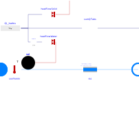
Extends from IDEAS.Fluid.Interfaces.LumpedVolumeDeclarations (Declarations for lumped volumes), IDEAS.Fluid.Interfaces.PartialTwoPortInterface (Partial model with two ports and declaration of quantities that are used by many models), IDEAS.Fluid.Interfaces.TwoPortFlowResistanceParameters (Parameters for flow resistance for models with two ports).
Information
Dynamic model of an embedded pipe for a concrete core activation. This model is based on (Koschenz, 2000). In addition the model provides the options to simulate the concrete core activation as if there were multiple parallel branches. This affects the pressure drop calculation and also the thermal calculations.
Assumptions and limitations
The implementation of Koschenz mentions that a minimum
discretization (i.e. using nDiscr) is required to avoid violation of the
second law of thermodynamics. The model explicitly
enforces the second law even for nDiscr=1 by upper bounding
the heat flow rate such that this minimum discretization does not apply to our implementation.
The parameter nDiscr thus
only affects the results at larger flow rates.
The example
IDEAS.Fluid.HeatExchangers.RadiantSlab.Examples.EmbeddedPipeNDiscr provides an indication
of the sensitivity of the results to the value of nDiscr.
The embeddedPipe model is designed to be used together with an
IDEAS.Buildings.Components.InternalWall.
When nDiscr>1, the wall/floor should also be discretized to be physically correct,
although the discretizations can also be connected to the same wall/floor, which gives a reasonable
approximation as illustrated by the example
IDEAS.Fluid.HeatExchangers.RadiantSlab.Examples.EmbeddedPipeNDiscr.
R_x_val represents thermal resistance between
the outer pipe wall temperature and the (fictive) uniform TABS temperature.
For small concrete/screed layer thicknesses (di ≤ 0.3·T, with T the distance between the pipes),
a correction factor needs to be taken into account (see Eq.4-4 and 4-24 in (Koschenz, 2000)).
R_w_val represents the convective thermal resistance between
the embedded pipe wall and the water flowing in that pipe.
Depending on the Reynolds number rey, laminar or turbulent flow is assumed.
For turbulent flow, the convective heat transfer coefficient is determined using a correlation (Eq.4-37) from (Koschenz, 2000).
For laminar flow, the convective heat transfer coefficent is calculated using a constant Nusselt number of 4.
Typical use and important parameters
Following parameters need to be set:
- RadSlaCha is a record with all the parameters of the geometry, materials, and even number of discretization layers in the nakedTabs model.
-
mFlow_minis used to check the validity of the operating conditions and is by default half of the nominal mass flow rate. -
A_flooris the surface area of (one side of) the radiant slab. -
nDiscrcan be used for discretizing the EmbeddedPipe along the flow direction. See above for a more detailed discussion. -
nParCircan be used for calculating the pressure drops as if there were multiple EmbeddedPipes connected in parallel. The total mass flow rate is then split over multiple circuits and the pressure drop is calculated accordingly. -
R_Cis the thermal resistivity from the center of the TABS or floor heating system to the zones. Note that the upper and lower resistivities need to be calculated as if they were in parallel. This parameter has a default value based on RadSlaCha but it may be improved if necessary. The impact of the value of this parameter on the model performance is low except in cases of very low mass flow rates.
Options
By default dp_nominal is calculated by making an estimate of the total pipe length.
This pressure drop can be an underestimation of the real pressure drop.
The used pipe lengths can be changed in the Pressure drop tab.
Parameter dp_nominal can be used to override the default calculation.
Validation
A limited verification has been performed in IDEAS.Fluid.HeatExchangers.RadiantSlab.Examples.EmbeddedPipeVerification.
References
EN 15377, Heating systems in buildings – Design of embedded water-based surface heating and cooling systems., 2008.
M. Koschenz and B. Lehmann, Thermoaktive Bauteilsysteme tabs. Dübendorf, Switzerland: EMPA Energyiesysteme/Haustechnik, 2000, ISBN: 9783905594195.
Transsolar, TRNSYS 16 - A TRaNsient SYstem Simulation program, User Manual. Volume 6: Multizone Building modeling with Type56 and TRNBuild. Madison, 2007.
Parameters
| Type | Name | Default | Description |
|---|---|---|---|
| IDEAS.Fluid.HeatExchangers.RadiantSlab.BaseClasses.RadiantSlabChar | RadSlaCha | ||
| Modelica.Units.SI.Length | pipeDiaInt | RadSlaCha.d_a - 2*RadSlaCha.s_r | Pipe internal diameter |
| Modelica.Units.SI.Area | A_floor | TABS or floor heating surface area | |
| Integer | nDiscr | 1 | Number of series discretisations along the flow direction |
| Real | nParCir | 1 | Number of parallel circuits in the tabs |
| Modelica.Units.SI.ThermalInsulance | R_r_val | RadSlaCha.T*log(RadSlaCha.d_a/pipeDiaInt)/(2*Modelica.Constants.pi*RadSlaCha.lambda_r) | Fixed thermal resistance value of thermal conduction through pipe wall * surface of floor between 2 pipes (see RadSlaCha documentation) |
| Modelica.Units.SI.ThermalInsulance | R_x_val | RadSlaCha.T*(log(RadSlaCha.T/(3.14*RadSlaCha.d_a)) + corr)/(2*Modelica.Constants.pi*RadSlaCha.lambda_b) | Fixed thermal resistance value of thermal conduction from pipe wall to layer |
| Real | corr | if RadSlaCha.S_1/RadSlaCha.T > 0.3 and RadSlaCha.S_2/RadSlaCha.T > 0.3 and RadSlaCha.d_a/RadSlaCha.T < 0.2 then 0 else sum(((RadSlaCha.alp1/RadSlaCha.lambda_b*RadSlaCha.T - 2*Modelica.Constants.pi*s)/(RadSlaCha.alp1/RadSlaCha.lambda_b*RadSlaCha.T + 2*Modelica.Constants.pi*s)*exp(-4*Modelica.Constants.pi*s/RadSlaCha.T*RadSlaCha.S_2) + (RadSlaCha.alp2/RadSlaCha.lambda_b*RadSlaCha.T - 2*Modelica.Constants.pi*s)/(RadSlaCha.alp2/RadSlaCha.lambda_b*RadSlaCha.T + 2*Modelica.Constants.pi*s)*exp(-4*Modelica.Constants.pi*s/RadSlaCha.T*RadSlaCha.S_1) - 2*exp(-4*Modelica.Constants.pi*s/RadSlaCha.T*(RadSlaCha.S_1 + RadSlaCha.S_2)))/(exp(-4*Modelica.Constants.pi*s/RadSlaCha.T*(RadSlaCha.S_1 + RadSlaCha.S_2)) - (RadSlaCha.alp1/RadSlaCha.lambda_b*RadSlaCha.T + 2*Modelica.Constants.pi*s)/(RadSlaCha.alp1/RadSlaCha.lambda_b*RadSlaCha.T - 2*Modelica.Constants.pi*s)*(RadSlaCha.alp2/RadSlaCha.lambda_b*RadSlaCha.T + 2*Modelica.Constants.pi*s)/(RadSlaCha.alp2/RadSlaCha.lambda_b*RadSlaCha.T - 2*Modelica.Constants.pi*s)) for s in 1:10) | Correction factor if the screed thickness(es) are too small compared to the pipe spacing and/or the pipe diameter is too large compared to the pipe spacing (Koschenz, 2000, Eq.4-24). The summation goes to 10 instead of infinity as this does not improve the accuracy. |
| Dynamics › Conservation equations | |||
| Modelica.Fluid.Types.Dynamics | energyDynamics (from LumpedVolumeDeclarations) | Modelica.Fluid.Types.Dynamics.DynamicFreeInitial | Type of energy balance: dynamic (3 initialization options) or steady state |
| Modelica.Fluid.Types.Dynamics | substanceDynamics (from LumpedVolumeDeclarations) | energyDynamics | Type of independent mass fraction balance: dynamic (3 initialization options) or steady state |
| Modelica.Fluid.Types.Dynamics | traceDynamics (from LumpedVolumeDeclarations) | energyDynamics | Type of trace substance balance: dynamic (3 initialization options) or steady state |
| Advanced › Dynamics | |||
| Modelica.Fluid.Types.Dynamics | massDynamics (from LumpedVolumeDeclarations) | energyDynamics | Type of mass balance: dynamic (3 initialization options) or steady state, must be steady state if energyDynamics is steady state |
| Initialization | |||
| Medium.AbsolutePressure | p_start (from LumpedVolumeDeclarations) | Medium.p_default | Start value of pressure |
| Medium.Temperature | T_start (from LumpedVolumeDeclarations) | Medium.T_default | Start value of temperature |
| Medium.MassFraction[Medium.nX] | X_start (from LumpedVolumeDeclarations) | Medium.X_default | Start value of mass fractions m_i/m |
| Medium.ExtraProperty[Medium.nC] | C_start (from LumpedVolumeDeclarations) | fill(0, Medium.nC) | Start value of trace substances |
| Medium.ExtraProperty[Medium.nC] | C_nominal (from LumpedVolumeDeclarations) | fill(1E-2, Medium.nC) | Nominal value of trace substances. (Set to typical order of magnitude.) |
| Dynamics | |||
| Real | mSenFac (from LumpedVolumeDeclarations) | 1 | Factor for scaling the sensible thermal mass of the volume |
| Assumptions | |||
| Boolean | allowFlowReversal (from PartialTwoPort) | true | = false to simplify equations, assuming, but not enforcing, no flow reversal |
| Nominal condition | |||
| Modelica.Units.SI.MassFlowRate | m_flow_nominal (from PartialTwoPortInterface) | Nominal mass flow rate | |
| Modelica.Units.SI.PressureDifference | dp_nominal (from TwoPortFlowResistanceParameters) | Pressure difference | |
| Modelica.Units.SI.MassFlowRate | m_flowMin | m_flow_nominal*0.5 | Minimal mass flow rate when in operation - used for validity check |
| Advanced | |||
| Modelica.Units.SI.MassFlowRate | m_flow_small (from PartialTwoPortInterface) | 1E-4*abs(m_flow_nominal) | Small mass flow rate for regularization of zero flow |
| Boolean | homotopyInitialization | true | = true, use homotopy method |
| Boolean | linearized | false | = true, use linear relation between m_flow and dp for any mass flow rate |
| Advanced › Diagnostics | |||
| Boolean | show_T (from PartialTwoPortInterface) | false | = true, if actual temperature at port is computed |
| Flow resistance | |||
| Boolean | computeFlowResistance (from TwoPortFlowResistanceParameters) | true | =true, compute flow resistance. Set to false to assume no friction |
| Boolean | from_dp (from TwoPortFlowResistanceParameters) | false | = true, use m_flow = f(dp) else dp = f(m_flow) |
| Boolean | linearizeFlowResistance (from TwoPortFlowResistanceParameters) | false | = true, use linear relation between m_flow and dp for any flow rate |
| Real | deltaM (from TwoPortFlowResistanceParameters) | 0.1 | Fraction of nominal flow rate where flow transitions to laminar |
| Modelica.Units.SI.Length | roughness | 2.5e-5 | Absolute roughness of pipe, with a default for a smooth steel pipe |
| Modelica.Units.SI.Length | L_floor | A_floor^(1/2) | Floor length, along the pipe direction |
| Real | N_pipes | A_floor/L_floor/RadSlaCha.T - 1 | Number of parallel pipes in the slab |
| Modelica.Units.SI.Length | pipeBendEqLen | 2*(N_pipes - 1)*(2.267*RadSlaCha.T/2/pipeDiaInt + 6.18)*pipeDiaInt | Pipe bends equivalent length, default according to Fox and McDonald (chapter 8.7, twice the linearized losses of a 90 degree bend) |
| Modelica.Units.SI.Length | pipeEqLen | pipeBendEqLen + (L_floor - 2*RadSlaCha.T)*N_pipes | Total pipe equivalent length, default assuming 180 dg turns starting at RadSlaCha.T from the end of the slab |
| Thermal | |||
| Modelica.Units.SI.ThermalInsulance | R_c | 1/(RadSlaCha.lambda_b/RadSlaCha.S_1 + RadSlaCha.lambda_b/RadSlaCha.S_2) | Specific thermal resistivity of (parallel) slabs connected to top and bottom of TABS / floor heating system |
Connectors
| Type | Name | Default | Description |
|---|---|---|---|
| Modelica.Fluid.Interfaces.FluidPort_a | port_a (from PartialTwoPort) | Fluid connector a (positive design flow direction is from port_a to port_b) | |
| Modelica.Fluid.Interfaces.FluidPort_b | port_b (from PartialTwoPort) | Fluid connector b (positive design flow direction is from port_a to port_b) | |
| Modelica.Thermal.HeatTransfer.Interfaces.HeatPort_b | heatPortEmb | Port to the core of a floor heating/concrete activation | |
| Modelica.Blocks.Interfaces.RealOutput | QTot | Total thermal power going into the heat port |
Components
| Type | Name | Default | Description |
|---|---|---|---|
| Modelica.Units.SI.MassFlowRate | m_flow (from PartialTwoPortInterface) | port_a.m_flow | Mass flow rate from port_a to port_b (m_flow > 0 is design flow direction) |
| Modelica.Units.SI.PressureDifference | dp (from PartialTwoPortInterface) | port_a.p - port_b.p | Pressure difference between port_a and port_b |
| Medium.ThermodynamicState | sta_a (from PartialTwoPortInterface) | if allowFlowReversal then Medium.setState_phX(port_a.p, noEvent(actualStream(port_a.h_outflow)), noEvent(actualStream(port_a.Xi_outflow))) else Medium.setState_phX(port_a.p, noEvent(inStream(port_a.h_outflow)), noEvent(inStream(port_a.Xi_outflow))) | Medium properties in port_a |
| Medium.ThermodynamicState | sta_b (from PartialTwoPortInterface) | if allowFlowReversal then Medium.setState_phX(port_b.p, noEvent(actualStream(port_b.h_outflow)), noEvent(actualStream(port_b.Xi_outflow))) else Medium.setState_phX(port_b.p, noEvent(port_b.h_outflow), noEvent(port_b.Xi_outflow)) | Medium properties in port_b |
| Modelica.Units.SI.Temperature | Tin | cat(1, {senTemIn.T}, vol[1:nDiscr - 1].heatPort.T) | |
| Modelica.Units.SI.Power | Q | Thermal power going into the TABS / floor heating system | |
| Modelica.Units.SI.ThermalInsulance | R_w_val | IDEAS.Utilities.Math.Functions.spliceFunction(x = rey - (reyHi + reyLo)/2, pos = RadSlaCha.T^0.13/8/Modelica.Constants.pi*abs((pipeDiaInt/(m_flowSpLimit*L_r)))^0.87, neg = RadSlaCha.T/(4*Medium.thermalConductivity(sta_default)*Modelica.Constants.pi), deltax = (reyHi - reyLo)/2) | Flow dependent resistance value of convective heat transfer inside pipe for both turbulent and laminar heat transfer. |
| Modelica.Units.SI.ThermalInsulance | R_t | Total equivalent specific resistivity as defined by Koschenz in eqn 4-59 | |
| Modelica.Units.SI.ThermalConductance | G_t | Equivalent thermal conductance | |
| Modelica.Units.SI.ThermalConductance | G_max | Maximum thermal conductance based on mass flow rate | |
| Modelica.Units.SI.ReynoldsNumber | rey | m_flow/nParCir/A_pipe*pipeDiaInt/mu_default | Reynolds number |
| IDEAS.Fluid.MixingVolumes.MixingVolume | vol | ||
| FixedResistances.ParallelPressureDrop | res | ||
| Modelica.Thermal.HeatTransfer.Sources.PrescribedHeatFlow | heatFlowWater | Heat flow rate that is extracted from the fluid | |
| Modelica.Thermal.HeatTransfer.Sources.PrescribedHeatFlow | heatFlowSolid | Heat flow rate that is injected in the solid material | |
| Modelica.Blocks.Math.Gain | negate | ||
| Modelica.Blocks.Sources.RealExpression | Q_tabs | ||
| Modelica.Blocks.Math.Sum | sumQTabs | Block that sums the volume heat flow rates | |
| Sensors.TemperatureTwoPort | senTemIn | Sensor for inlet temperature |
Revisions
-
August 12, 2025, by Jelger Jansen:
Fix correction term and wrong asserts and update documentation.
See #1381. -
March 20, 2020 by Filip Jorissen:
Fixed inconsistency in the mass computation of the MixingVolume. See #1116. -
January 31, 2020 by Filip Jorissen:
PropagatedallowFlowReversalinTemperatureTwoPortsensor. See #1105. -
October 19, 2019 by Filip Jorissen:
Removed discretization assert since we limit the heat flow rate to physically realistic values already using a limit onG_t. Revised documentation. See #863. -
October 18, 2019 by Filip Jorissen:
UsingTemperatureTwoPortsensor. See #1081. -
October 13, 2019 by Filip Jorissen:
Bugfix for division by zero whendp_nominal=0, See #1031. -
August 14, 2019 by Iago Cupeiro:
Added output that computes the total TABS heat flow of theEmbeddedPipe. -
April 16, 2019 by Filip Jorissen:
Added checks for flow reversal. See #1006. -
April 16, 2019 by Filip Jorissen:
RemovedcomputeFlowResistance=falsesince this parameter was hidden in the advanced tab and this setting can easily lead to singularities. See #1014. -
June 21, 2018 by Filip Jorissen:
Setfinal alpha=0inprescribedHeatFlowto avoid large algebraic loops in specific cases. See #852. -
April 26, 2017 by Filip Jorissen:
RemoveduseSimplifiedRtparameter since this leads to a violation of the second law for small flow rates. See #717. -
November, 2015, by Filip Jorissen:
Revised implementation for small flow rates. -
2015, by Filip Jorissen:
Revised implementation -
March, 2014, by Filip Jorissen:
IDEAS baseclasses -
May, 2013, by Roel De Coninck:
Documentation -
April, 2012, by Roel De Coninck:
Rebasing on common Partial_Emission - 2011, by Roel De Coninck: First version and validation