modelATPIrelayNCmixedMode
PI controller with Auto Tuning algorithm - mixed continuous/discrete time version -

Extends from IndustrialControlSystems.Controllers.Interfaces.Controller (Partial interface for a generic controller).
Information
Description
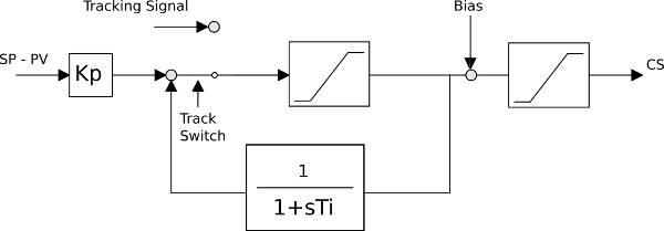
Proportional + Integral controller with AutoTuning, Automatic, Tracking mode and bias signal.
The control law is defined as
              1+sTi
  CS(s) = Kp ------- (SP(s) - PV(S))
               sTi
Scheme
| Name | Description | Conditional? |
|---|---|---|
| SP | Set Point | NO |
| PV | Process Variable | NO |
| CS | Control Signal | NO |
| TR | Track Reference signal | YES (useTS) |
| TS | Track Switch signal | YES (useTS) |
| Bias | Biasing signal | YES (useBIAS) |
| ATreq | AutoTuning request | YES (useAT) |
The controller can have various operating conditions:
- Automatic,
- Auto Tuning,
- and Tracking
In the Automatic mode, the control output is computed with the proportional+integral control law, while in the tracking mode
it is defined by the input TR.
Auto Tuning
This section presents the Modelica realisations of the fully digital of the considered autotuning methodology. The block inputs are the set point (SP) and the process variable (PV), plus a boolean one, a pulse on which initiates the autotuning procedure; the output is clearly the control signal (CS). The initial values for K and Ti, as well as the required phase margin pm, are provided as parameters. The autotuning procedure is composed of the following steps:
- start with the controller in PI mode;
- when the AT pulse is received,
- initialise the relay plus integrator control,
- connect it to the process,
- and wait for a permanent oscillation;
- when a permanent oscillation is detected, compute its frequency (wox), and by means of the following equation
determine the corresponding process frequency response magnitude (the phase is -90 degrees);
Pox := pi^2*(rPVmax-rPVmin)/8/(rCSmax-rCSmin)
- apply equations
  TI     := tan(pm/180*pi)/wox
  K      := tan(pm/180*pi)/(Pox*sqrt(1+(tan(pm/180*pi))^2))
to tune the regulator, and finally switch back to PI mode.
It is worth noticing that any industrial realisation would be more articulated than those illustrated in the following. For example, some logic would need introducing to abort the procedure in the case of unexpected and/or possibly harmful system behaviours, a confirmation should be requested to the operator in order to accept or decline the proposed parameters prior to updating the PI, and so forth. Such features are however omitted here since they are lengthy to discuss in the necessary detail, and substantially inessential for the purpose of this work.
Mixed Mode
When everything is digital, things are simple, and the only issue to care about is to correctly manage the regulator tracking while the relay is driving the control signal so as to achieve the required permanent oscillation. If conversely one wants to represent the controller as a continuous-time system, it is necessary to suitably coordinate it with the digital procedure. The solution adopted here can be summarised as follows. First, implement the controller in the desired form (here, for consistence with the digital case, an antiwindup PI was chosen) as differential and algebraic equations. Then, realise the autotuning procedure as a digital algorithm, including the control computation during that procedure, exactly as it was in the fully digital case. Finally, manage the autotuning request event by (a) setting a flag that selects the control output to be that coming from the equations or the algorithm, depending on the mode, and (b) initialising the algorithm output to the last equation output. Analogously, manage the autotuning termination by resetting the above flag, and reinitialising the equation-based controller state to match the last algorithm output. The only (small) disadvantage of such a solution is that the equation-based controller stays in place during the autotuning phase. However the resulting overhead is generally very limited, given the invariantly simple structure of the controller, while there is a gain in terms of simplicity with respect to possible alternative solutions attempting to avoid said overhead.References
For more information please refers to the following paper:Efficient hybrid simulation of autotuning PI controllers
Alberto Leva, Marco Bonvini
8th Modelica Conference, Dresden, Germany
march 20-22, 2011
Parameters
| Type | Name | Default | Description |
|---|---|---|---|
| Real | eps (from Controller) | 1e-1 | small time constant that represents the time for switching between auto and tracking mode |
| Boolean | useTS (from Controller) | false | =true, if TS and TR inputs are enabled |
| Boolean | useBIAS (from Controller) | false | =true, if BIAS input is enabled |
| Boolean | useAT (from Controller) | false | =true, if AutoTuning input is enabled |
| Boolean | useGS (from Controller) | false | =true, if GainScheduling inputs are enabled |
| Boolean | useSAT (from Controller) | false | =true, if Saturation outputs are enabled |
| Discretisation | |||
| Real | Ts (from Controller) | 0 | Sampling time (if <= 0 continuous time) |
| IndustrialControlSystems.LinearSystems.Discrete.Types.discrMethod | method (from Controller) | IndustrialControlSystems.LinearSystems.Discrete.Types.discrMethod.BE | Discretisation method |
| Saturation | |||
| Boolean | AntiWindup (from Controller) | false | Flag that enables the antiwindup feature |
| Real | CSmin (from Controller) | 0 | minimum value of the CS |
| Real | CSmax (from Controller) | 1 | maximum value of the CS |
| Initialisation | |||
| Real | CS_start (from Controller) | 0 | output initial value |
| Parameters | |||
| Real | Kp | 5 | Proportional gain (initial value) |
| Real | Ti | 1 | Integral time (initial value) |
| Auto Tuning Algorithm | |||
| Real | slope | 1 | Slope of the signal |
| Real | permOxPeriodPerc | 5 | allowed % difference between period measurements |
| Real | pm | 45 | Phase Margin required |
| Integer | nOxMin | 3 | minimum number of oscillations |
Connectors
| Type | Name | Default | Description |
|---|---|---|---|
| Modelica.Blocks.Interfaces.RealInput | TR (from Controller) | Track Reference signal | |
| Modelica.Blocks.Interfaces.BooleanInput | TS (from Controller) | Track Switch signal | |
| Modelica.Blocks.Interfaces.RealInput | BIAS (from Controller) | Bias | |
| Modelica.Blocks.Interfaces.RealInput | SP (from Controller) | Set Point signal | |
| Modelica.Blocks.Interfaces.RealOutput | CS (from Controller) | Control signal | |
| Modelica.Blocks.Interfaces.RealInput | PV (from Controller) | Process Variable signal | |
| Modelica.Blocks.Interfaces.BooleanInput | ATreq (from Controller) | Auto Tuning request | |
| Modelica.Blocks.Interfaces.BooleanOutput | satHI (from Controller) | ||
| Modelica.Blocks.Interfaces.BooleanOutput | satLOW (from Controller) |
Components
| Type | Name | Default | Description |
|---|---|---|---|
| Real | bias (from Controller) | bias signal | |
| Real | tr (from Controller) | track reference value | |
| Boolean | ts (from Controller) | track reference signal | |
| Boolean | at_req (from Controller) | auto tuning enabling signal | |
| Boolean | satHigh (from Controller) | High saturation signal | |
| Boolean | satLow (from Controller) | Low saturation signal | |
| Integer | iMode | ||
| Real | K | ||
| Real | TI |
Revisions
- Industrial Control Systems (v 1.0.0) : April-May 2012
- List of revisions:
- 11 May 2012 (author: Marco Bonvini)
- Main Authors:
- Marco Bonvini; <bonvini@elet.polimi.it>
- Alberto Leva <leva@elet.polimi.it>
- Politecnico di Milano
- Dipartimento di Elettronica e Informazione
- Via Ponzio 34/5
- 20133 Milano - ITALIA -
- Copyright:
- Copyright © 2010-2012, Marco Bonvini and Alberto Leva.
- The IndustrialControlSystems package is free software; it can be redistributed and/or modified under the terms of the Modelica license.