This is a simple drive train controlled by a PID controller:
The PI controller is initialized in steady state (initType=SteadyState) and the drive shall also be initialized in steady state. However, it is not possible to initialize "inertia1" in SteadyState, because "der(inertia1.phi)=inertia1.w=0" is an input to the PI controller that defines that the derivative of the integrator state is zero (= the same condition that was already defined by option SteadyState of the PI controller). Furthermore, one initial condition is missing, because the absolute position of inertia1 or inertia2 is not defined. The solution shown in this examples is to initialize the angle and the angular acceleration of "inertia1".
In the following figure, results of a typical simulation are shown:
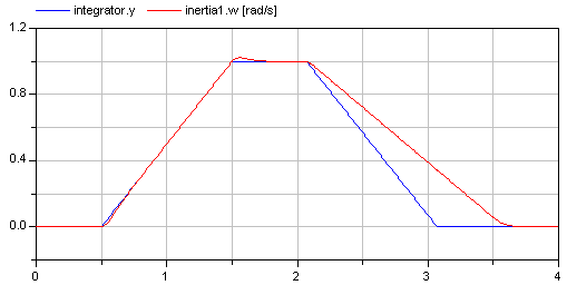
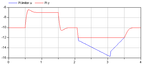
In the upper figure the reference speed (= integrator.y) and the actual speed (= inertia1.w) are shown. As can be seen, the system initializes in steady state, since no transients are present. The inertia follows the reference speed quite good until the end of the constant speed phase. Then there is a deviation. In the lower figure the reason can be seen: The output of the controller (PI.y) is in its limits. The anti-windup compensation works reasonably, since the input to the limiter (PI.limiter.u) is forced back to its limit after a transient phase.