This controller can be used both for DC/DC and AC/DC converters.
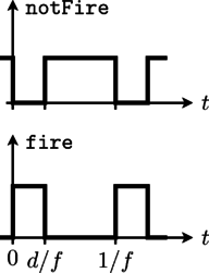
The signal input of the PWM controller is the duty cycle; the duty
cycle is the ratio of the on time to the switching period. The
output firing signal is strictly determined by the actual duty
cycle, indicated as d in Fig. 1.
 |
The firing signal is generated by comparing the sampled duty cycle input with a periodic saw tooth [Williams2006] or triangular signal (carrier).
The user has the choice between two comparison modes:
commonComparison = true : The result of the comparison dutyCyle > carrier is fed to fire_p, the inverse signal to fire_n.
commonComparison = false: The result of the comparison dutyCyle > carrier is fed to fire_p, the result of the comparison (1 - dutyCyle) > carrier is fed to fire_n. (The result is the same for the comparison dutyCycle > (1 - carrier), i.e. a signal shifted by 180°.)