This library is designed in a fully object oriented way in order that components can be connected together in every meaningful combination (e.g., direct connection of two springs or two inertias). As a consequence, most models lead to a system of differential-algebraic equations (DAE) of index 3 (= constraint equations have to be differentiated twice in order to arrive at a state space representation) and the Modelica translator or the simulator has to cope with this system representation. According to our present knowledge, this requires that the Modelica translator is able to symbolically differentiate equations (otherwise it is e.g., not possible to provide consistent initial conditions; even if consistent initial conditions are present, most numerical DAE integrators can cope at most with index 2 DAEs).
The elements of this library can be connected together in an arbitrary way. However, difficulties may occur, if the elements which can lock the relative motion between two flanges are connected rigidly together such that essentially the same relative motion can be locked. The reason is that the cut-torque in the locked phase is not uniquely defined if the elements are locked at the same time instant (i.e., there does not exist a unique solution) and some simulation systems may not be able to handle this situation, since this leads to a singularity during simulation. Currently, this type of problem can occur with the Coulomb friction elements such as BearingFriction, Clutch, Brake or LossyGear when the elements become stuck:
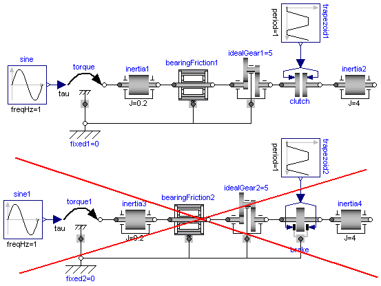
In the figure above, two typical situations are shown: In the
upper part of the figure, the series connection of rigidly attached
bearingFriction1 and clutch components
are shown. This does not hurt, because the
bearingFriction1 element can lock the relative motion
between the element and the housing (fixed1), whereas
the clutch element can lock the relative motion between the two
connected flanges. On the contrary, the drive train in the lower
part of the figure may give rise to simulation problems, because
the bearingFriction2 element and the
brake element can lock the relative motion between a
flange and the housing and these flanges are rigidly connected
together, i.e., essentially the same relative motion can be locked.
These difficulties may be solved by either introducing a compliance
between these flanges or by combining the bearing friction and
brake element into one component and resolving the ambiguity of the
frictional torque in the stuck mode of that component. A tool may
handle this situation also automatically, by
picking one solution of the infinitely many, e.g., the one where
the difference to the value of the previous time instant is as
small as possible.