
modelAD_DA_conversion
Conversion circuit
Extends from Modelica.Icons.Example (Icon for runnable examples).
Information
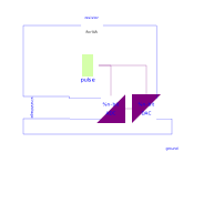
The simple converter circuit converts an analog sine signal into a N-bit (by default a 4 bit) logic signal, which is converted backward into an analog signal.
- Simulate for 0.2 s.
Compare the input voltage (aD_Converter.p.v) with the output voltage (dA_Converter.p.v). By changing N the influence of the digital signal width can be studied. Otherwise the trigger frequency pulse.period can be changed to see its influence.
Parameters
| Type | Name | Default | Description |
|---|---|---|---|
| Integer | N | 7 | Digital signal width |
Components
| Type | Name | Default | Description |
|---|---|---|---|
| Modelica.Electrical.Analog.Ideal.AD_Converter | aD_Converter | ||
| Modelica.Electrical.Digital.Sources.Pulse | pulse | ||
| Modelica.Electrical.Analog.Ideal.DA_Converter | dA_Converter | ||
| Modelica.Electrical.Analog.Basic.Ground | ground | ||
| Modelica.Electrical.Analog.Sources.SineVoltage | sineVoltage | ||
| Modelica.Electrical.Analog.Basic.Resistor | resistor |
Revisions
- October 13, 2009 by Matthias Franke