
modelSMR_Inverter
Test example: SynchronousMachineReluctanceRotor with inverter
Extends from Modelica.Icons.Example (Icon for runnable examples).
Information
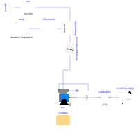
An ideal frequency inverter is modeled by using a VfController and a three-phase SignalVoltage. Frequency is raised by a ramp, causing the reluctance machine to start, and accelerating inertias. At time tStep a load step is applied.
Simulate for 1.5 seconds and plot (versus time):
- currentQuasiRMSSensor.I: stator current RMS
- smr.wMechanical: motor's speed
- smr.tauElectrical: motor's torque
- rotorDisplacementAngle.rotorDisplacementAngle: rotor displacement angle
Default machine parameters are used.
Parameters
| Type | Name | Default | Description |
|---|---|---|---|
| Integer | m | 3 | Number of phases |
| SI.Voltage | VNominal | 100 | Nominal RMS voltage per phase |
| SI.Frequency | fNominal | 50 | Nominal frequency |
| SI.Frequency | f | 50 | Actual frequency |
| SI.Time | tRamp | 1 | Frequency ramp |
| SI.Torque | TLoad | 46 | Nominal load torque |
| SI.Time | tStep | 1.2 | Time of load torque step |
| SI.Inertia | JLoad | 0.29 | Load's moment of inertia |
| Utilities.ParameterRecords.SM_ReluctanceRotorData | smrData | Synchronous machine data |
Components
| Type | Name | Default | Description |
|---|---|---|---|
| Machines.BasicMachines.SynchronousMachines.SM_ReluctanceRotor | smr | ||
| Machines.Sensors.CurrentQuasiRMSSensor | currentQuasiRMSSensor | ||
| Machines.Sensors.RotorDisplacementAngle | rotorDisplacementAngle | ||
| Modelica.Blocks.Sources.Ramp | ramp | ||
| Machines.Utilities.VfController | vfController | ||
| Modelica.Electrical.Polyphase.Sources.SignalVoltage | signalVoltage | ||
| Modelica.Electrical.Polyphase.Basic.Star | star | ||
| Modelica.Electrical.Analog.Basic.Ground | ground | ||
| Modelica.Mechanics.Rotational.Components.Inertia | loadInertia | ||
| Modelica.Mechanics.Rotational.Sources.TorqueStep | loadTorqueStep | ||
| Machines.Utilities.TerminalBox | terminalBox |