
modelSMR_Inverter_Polyphase
Starting of polyphase synchronous reluctance machine with inverter
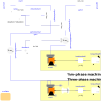
Extends from Modelica.Icons.Example (Icon for runnable examples).
Information
Synchronous machine with reluctance rotor fed by an ideal inverter
Ideal frequency inverters are modeled by using a
VfController
and phase SignalVoltages.
Frequency is raised by a ramp, causing the
reluctance machine to start,
and accelerating inertias. At time tStep a load step is applied. Two equivalent machines with different numbers of phases are compared and their equal behavior is demonstrated.
Simulate for 1.5 seconds and plot (versus time):
aimcM|M3.tauElectrical: machine torqueaimsM|M3.wMechanical: machine speedfeedback.y: zero since difference of three-phase current phasor and scaled polyphase current phasor are equal
Parameters
| Type | Name | Default | Description |
|---|---|---|---|
| Integer | m3 | 3 | Number of stator phases of three-phase system |
| Integer | m | 5 | Number of stator phases |
| SI.Voltage | VsNominal | 100 | Nominal RMS voltage per phase |
| SI.Frequency | fsNominal | smrData.fsNominal | Nominal frequency |
| SI.Frequency | fKnee | 50 | Knee frequency of V/f curve |
| SI.Time | tRamp | 1 | Frequency ramp |
| SI.Torque | T_Load | 46 | Nominal load torque |
| SI.Time | tStep | 1.2 | Time of load torque step |
| SI.Inertia | J_Load | 0.29 | Load inertia |
| Modelica.Electrical.Machines.Utilities.ParameterRecords.SM_ReluctanceRotorData | smrData | Synchronous machine data |