modelRotorWith3DEffects
Information
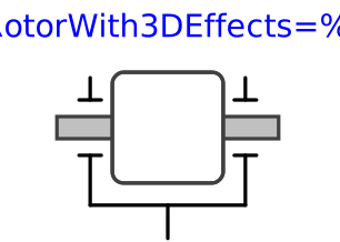
This component is used to model the gyroscopic torques exerted by a 1-dim.
inertia (so called rotor) on its 3-dim. carrier body. Gyroscopic torques
appear, if the vector of the carrier body's angular velocity is not parallel
to the vector of the rotor's axis. The axis of rotation of the rotor is defined by
the parameter n, which has to be given in the local coordinate system
of frame_a. The default animation of this component is
shown in the figure below.

This component is a replacement for Modelica.Mechanics.Rotational.Components.Inertia for the case, that a 1-dim.-rotational mechanical system should be attached with a 3-dim. carrier body.
The Boolean parameter exact was introduced due to performance
reasons. If exact is set to false, the influence of the carrier body
motion on the angular velocity of the rotor is neglected. This influence is usually
negligible if the 1-dim.-rotational mechanical system accelerates much faster as the base body (this is,
e.g., the case in vehicle powertrains). The essential advantage is
that an algebraic loop is removed since then there is only an
action on acceleration level from the powertrain to the base body
but not vice versa.
Reference
Schweiger, Christian ;
Otter, Martin:
Modelling
3D Mechanical Effects of 1-dim. Powertrains. In: Proceedings of the 3rd International
Modelica Conference. Linköping : The Modelica Association and Linköping University,
November 3-4, 2003, pp. 149-158
Parameters
| Type | Name | Default | Description |
|---|---|---|---|
| Boolean | animation | true | = true, if animation shall be enabled (show rotor as cylinder) |
| SI.Inertia | J | 1 | Moment of inertia of rotor around its axis of rotation |
| Types.Axis | n | {1, 0, 0} | Axis of rotation resolved in frame_a |
| Animation › if animation = true | |||
| SI.Position[3] | r_center | zeros(3) | Position vector from origin of frame_a to center of cylinder |
| SI.Distance | cylinderLength | 2*world.defaultJointLength | Length of cylinder representing the rotor |
| SI.Distance | cylinderDiameter | 2*world.defaultJointWidth | Diameter of cylinder representing the rotor |
| Advanced | |||
| StateSelect | stateSelect | StateSelect.default | Priority to use rotor angle (phi) and rotor speed (w) as states |
| Boolean | exact | true | = true, if exact calculations; false if influence of bearing on rotor acceleration is neglected to avoid an algebraic loop |
Connectors
| Type | Name | Default | Description |
|---|---|---|---|
| Modelica.Mechanics.Rotational.Interfaces.Flange_a | flange_a | (left) driving flange (flange axis directed INTO cut plane) | |
| Modelica.Mechanics.Rotational.Interfaces.Flange_b | flange_b | (right) driven flange (flange axis directed OUT OF cut plane) | |
| Modelica.Mechanics.MultiBody.Interfaces.Frame_a | frame_a | Frame in which rotor housing is fixed |
Components
| Type | Name | Default | Description |
|---|---|---|---|
| Types.Color | cylinderColor | Modelica.Mechanics.MultiBody.Types.Defaults.RodColor | Color of cylinder representing the rotor |
| Types.SpecularCoefficient | specularCoefficient | world.defaultSpecularCoefficient | Reflection of ambient light (= 0: light is completely absorbed) |
| SI.AngularVelocity[3] | w_a | Angular velocity of frame_a, resolved in frame_a | |
| SI.Angle | phi | Rotation angle of rotor with respect to frame_a (= flange_a.phi = flange_b.phi) | |
| SI.AngularVelocity | w | Angular velocity of rotor with respect to frame_a | |
| SI.AngularAcceleration | a | Angular acceleration of rotor with respect to frame_a |