functiontimeResponse
Plot the time response of a system represented by a transfer function. The response type is selectable
Extends from Modelica_LinearSystems2.Internal.PartialPlotFunction (Interface of a plot function).
Information
Syntax
ZerosAndPoles.Plot.timeResponse(zp);
   or
ZerosAndPoles.Plot.timeResponse(
  zp,
  dt,
  tSpan,
  response,
  x0,
  columnLabels,
  defaultDiagram=Modelica_LinearSystems2.Internal.DefaultDiagramTimeResponse(),
  device=Modelica_LinearSystems2.Utilities.Plot.Records.Device())
Description
This function plots the time response of a transfer function. The character of the time response if defined by the input response, i.e. Impulse, Step, Ramp, or Initial.
Example
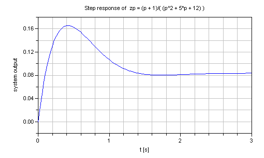
  ZerosAndPoles p = Modelica_LinearSystems2.ZerosAndPoles.p();
  Modelica_LinearSystems2.ZerosAndPoles zp =(p + 1)/(p^2 + 5*p + 12);

  Types.TimeResponse response = Modelica_LinearSystems2.Utilities.Types.TimeResponse.Step;

algorithm
  Modelica_LinearSystems2.ZerosAndPoles.Plot.timeResponse(zp, dt=0.02, tSpan=3, response=response)
//  gives:
See also
Inputs
| Type | Name | Default | Description |
|---|---|---|---|
| ZerosAndPoles | zp | ||
| Real | dt | 0 | Sample time [s] |
| Real | tSpan | 0 | Simulation time span [s] |
| TimeResponse | response | TimeResponse.Step | type of time response |
| Real[ZerosAndPoles.Analysis.denominatorDegree(zp)] | x0 | zeros(ZerosAndPoles.Analysis.denominatorDegree(zp)) | Initial state vector |
| Plot.Records.Diagram | defaultDiagram (from PartialPlotFunction) | Default diagram layout | |
| Plot.Records.Device | device (from PartialPlotFunction) | Modelica_LinearSystems2.Utilities.Plot.Records.Device() | Properties of device where figure is shown |