modelMaxTotalHarmonicDistortion

Extends from Internal.PartialFFT (Partial model containing the common part of the FFT blocks).
Information
Syntax
property = MaxTotalHarmonicDistortion(condition=..., u=..., f_resolution=..., f_base=...., n_harmonics=..., THDmax=...).y;
Description
Whenever the Boolean input condition has a rising edge, the Real input u is sampled and stored in a buffer. Once enough values of u are stored in the buffer (depending on parameters f_base, n_harmonics and f_resolution) a Fast Fourier Transform (FFT) of the buffer u-values is computed. The amplitudes and frequencies of the computed FFT are stored on file and displayed in the icon. The Total Harmonic Distortion (THD) of the amplitudes must be below the given limit THDmax (in [%]). The theoretical THD is defined as:
THD_theoretical = sqrt( sum( A(i*f_base)^2 ) ) / A(f_base); i = 2,3,...
where parameter f_base is the base frequency and A(f) is the amplitude at frequency f. The THD is computed within this block by using the maximum amplitude within a small interval around the higher harmonic frequencies (i*f_base; i=2,3,...).
After the FFT computation has been performed it is checked that the THD value is within the required limit:
THD ≤ THDmax
where THDmax is the maximum allowed THD value. The default value is 0.1 (so 10 %).
For more details, see the description of package ChecksInFixedWindow_withFFT.
Example
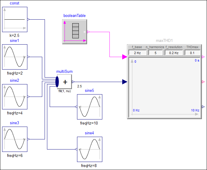
This block is demonstrated with the following first example:
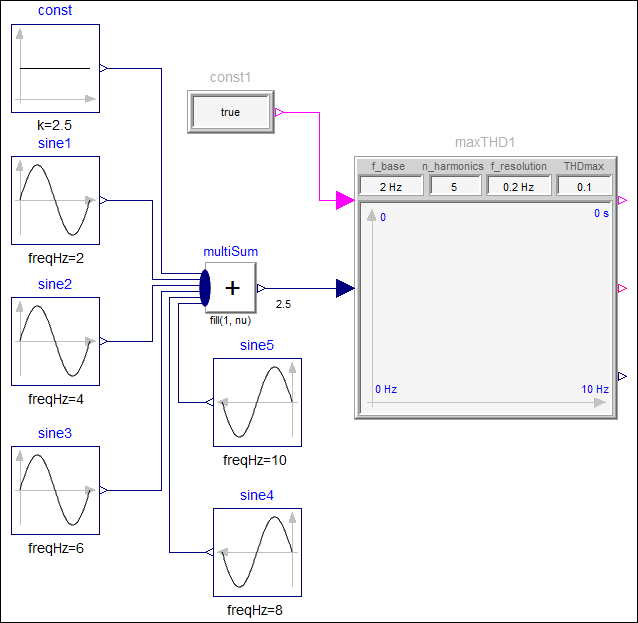
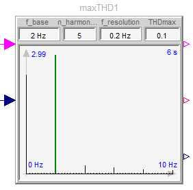
The amplitutes of the FFT are dynamically displayed in the icon of the block (in black). The amplitude of the base frequency is shown in green.
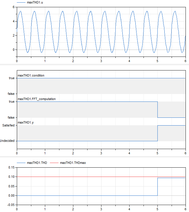
Simulating this examples results in
 |
|
| simulation result |
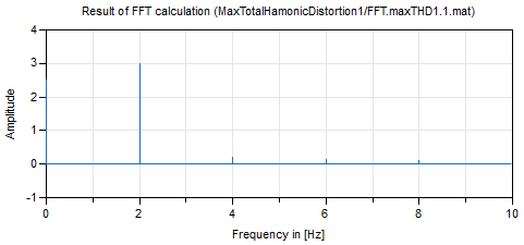
A plot of the FFT result file is shown in the next figure:
This block can be also used to compute several FFTs along a simulation as demonstrated with the following second example:
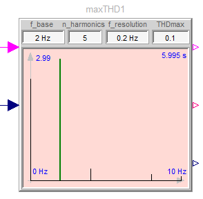
Since in the second FFT calculation the THD value is larger as THDmax, the icon is displayed in light red.
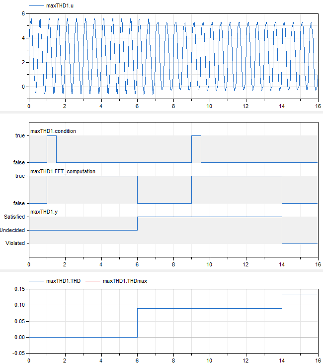
Simulating this examples results in
 |
|
| simulation result |
As can be seen, the first FFT fulfills the check (THD < THDmax), whereas the second FFT has a too large THD value.
Parameters
| Type | Name | Default | Description |
|---|---|---|---|
| Boolean | storeFFTonFile (from PartialFFT) | true | = true, if FFT results shall be stored on file <modelName>/FFT.<instanceName>.<index>.mat |
| Modelica.Units.SI.Frequency | f_max (from PartialFFT) | Maximum frequency of interest (sampling frequency >= 10*f_max) | |
| Modelica.Units.SI.Frequency | f_resolution (from PartialFFT) | Frequency resolution (frequency axis points are an integer multiple of f_resolution) | |
| Integer | ns (from PartialFFT) | Internal.get_ns(f_max, f_resolution) | Number of FFT sample points (is even and can be expressed as ns = 2^i*3^j*5^k) |
| Modelica.Units.SI.Frequency | f_max_FFT (from PartialFFT) | f_resolution*div(ns, 2) | Maximum frequency used by FFT |
| Integer | nf (from PartialFFT) | div(ns, 2) + 1 | Number of frequency points |
| Modelica.Units.SI.Time | Ts (from PartialFFT) | 1/(2*f_max_FFT) | Sample period |
| Modelica.Units.SI.Time | T (from PartialFFT) | (ns - 1)*Ts | Simulation time for one FFT calculation |
| Integer | np (from PartialFFT) | max(1, min(integer(ceil(f_max/f_resolution)) + 1, nf)) | Number of frequency points used for plotting (only up to interested frequency |
| Modelica.Units.SI.Frequency | f_max_plot (from PartialFFT) | (np - 1)*f_resolution | |
| Modelica.Units.SI.Frequency | f_base | Base frequency (100 % amplitude = largest amplitude around f_base) | |
| Integer | n_harmonics | 5 | Number of harmonics to treat for THD (f_max = n_harmonics*f_base; sampling frequency >= 10*f_max) |
| Real | THDmax | 0.1 | Total harmonic distortion limit |
| Advanced | |||
| Real | searchInterval | 5 | Search interval [%] around base frequency f_base for real base frequency (with largest amplitude) |
Connectors
| Type | Name | Default | Description |
|---|---|---|---|
| Modelica.Blocks.Interfaces.BooleanInput | condition (from PartialFFT) | Boolean input condition signal (a rising edge signals to store u-values in a buffer; if there are enough values in the buffer, an FFT is computed) | |
| Modelica.Blocks.Interfaces.RealInput | u (from PartialFFT) | Signal on which an FFT is performed | |
| Modelica_Requirements.Interfaces.PropertyOutput | y (from PartialFFT) | Property output signal (= Satisfied, if FFT Amplitudes of u are within maxAmplitude) | |
| Modelica.Blocks.Interfaces.BooleanOutput | FFT_computation (from PartialFFT) | = true, when u is stored in buffer for FFT computation | |
| Modelica.Blocks.Interfaces.RealOutput | scaledDistance (from PartialFFT) | Minimum distance of FFT Amplitudes of u to maxAmplitude (>= 0 if inside, otherwise outside of maxAmplitude) |
Components
| Type | Name | Default | Description |
|---|---|---|---|
| Boolean | periods_ok (from PartialFFT) | = true, if all periods for FFT computations have been long enough | |
| Integer[3] | fillColor (from PartialFFT) | if scaledDistance >= 0 then {245, 245, 245} else {255, 218, 213} | |
| Real[3*np,2] | fA_plot (from PartialFFT) | [frequency, amplitude] matrix used for plotting in icon | |
| Modelica.Units.SI.Frequency | f_base2 | Real base frequency (frequency with largest amplitude around f_base) | |
| Real | A_base2 | Amplitude at the real base frequency (= largest amplitude around f_base) | |
| Real | A_max_plot | Maximum amplitude of the FFT | |
| Real | THD | THD value | |
| Real[2,2] | f_base2_line |
Revisions
| Date | Description |
|---|---|
| Nov. 29, 2015 |
Initial version implemented by
Martin R. Kuhn and Martin Otter
(DLR Institute of System Dynamics and Control) The research leading to these results has received funding from the European Union’s Seventh Framework Programme (FP7/2007-2016) for the Clean Sky Joint Technology Initiative under grant agreement no. CSJU-GAM-SGO-2008-001. |