An important practical aspect of state machines is the ability to assign values and expressions to variables depending on the state of the machine. In StateGraph2, a number of graphical components have been added to package Modelica_StateGraph2.Blocks to facilitate usage in a safe and intuitive way. Since these are just input/output blocks and will also be useful in another context, it is planned to add them to the Modelica Standard Library.
There are a number of standard blocks with common operations/displays of the three basic types (Boolean, Integer, Real) using vector input connectors which enables them to be connected to an arbitrary number of sources. Resizing a vector port and connecting to the next free element is performed automatically when connecting to the connector. So this is much more convenient as with the Modelica.Blocks.Logical blocks. A vector of input connectors is visualized as an ellipse (see the violet ellipse on the left side of the multiSwitch components in the Figures below).
The most important action blocks are the MultiSwitch blocks for the different basic data types (MathBoolean.MultiSwitch, MathInteger.MultiSwitch, MathReal.MultiSwitch). These block select one of N (Boolean, Integer, or Real) expressions depending on an array of Boolean inputs. The index of the first input in the Boolean array that is true defines the index of the expression in the expression array to be used as the scalar output y.
 In the Figure to the right, the MultiSwitch
component will output the value y = 1 if Step s1 is active, and
will output y = 2 if s2 is active as the expression array is
defined as {1,2}. If none of the Boolean array inputs is true, the
"else" value will be used instead that is defined in the parameter
menu of the MultiSwitch component and is displayed below the icon.
Consider the Figure when Step s3 is active - this will set the
output of component "multiSwitch" to the "else" value "3".
Alternatively, in the parameter menu of the MultiSwitch component
it can be defined to keep its previous value, i.e., y =
pre(y). If this option would be selected for the Figure to
the right, then multiSwitch.y = 2 when Step s3 is active.
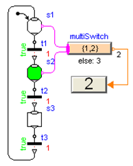
In the Figure to the right, the MultiSwitch
component will output the value y = 1 if Step s1 is active, and
will output y = 2 if s2 is active as the expression array is
defined as {1,2}. If none of the Boolean array inputs is true, the
"else" value will be used instead that is defined in the parameter
menu of the MultiSwitch component and is displayed below the icon.
Consider the Figure when Step s3 is active - this will set the
output of component "multiSwitch" to the "else" value "3".
Alternatively, in the parameter menu of the MultiSwitch component
it can be defined to keep its previous value, i.e., y =
pre(y). If this option would be selected for the Figure to
the right, then multiSwitch.y = 2 when Step s3 is active.
The MultiSwitch block is inspired by "Modes" from Mode Automata (Maraninchi and Rémond 2002, see Literature): Variable multiSwitch.y has always a unique value, and this value depends on the expressions that are associated with mutually exclusive active steps. The advantages of MultiSwitch are that (1) the definition is performed in a purely graphical way, (2) it can also be used for mutually non-exclusive active steps in a Parallel component, and (3) it can be implemented in Modelica in a very simple way. The drawback is that the expressions in the MultiSwitch block might no longer be so easy associated with Steps, compared to the alternative where the expressions are defined directly in the respective Steps. This latter approach would, however, require non-trivial extensions to the Modelica language.
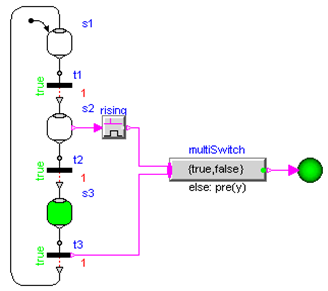
The RisingEdge, FallingEdge and ChangingEdge, components can be used to generate "pulse" signals depending on the rising, falling or changing values of a Boolean signal. An example is shown in the Figure below where the Boolean indicator lamp is turned on when Step s2 becomes active and is turned off when Transition t3 fires and Step s3 becomes inactive. Two variants are shown to utilize the "rising" property of a Boolean signal: The Boolean connectors at Steps and Transitions can be activated via parameters "use_activePort" and "use_firePort", respectively. If s2 becomes active, rising = true and therefore multiSwitch.y = true. If transition t3 fires, t3.firePort=true and therefore multiSwitch.y = false.