In this section an application example is shown, to demonstrate various features of the Modelica_StateGraph2 library. This example shows the control of a two tank system which is based on the master thesis of Isolde Dressler (see literature).
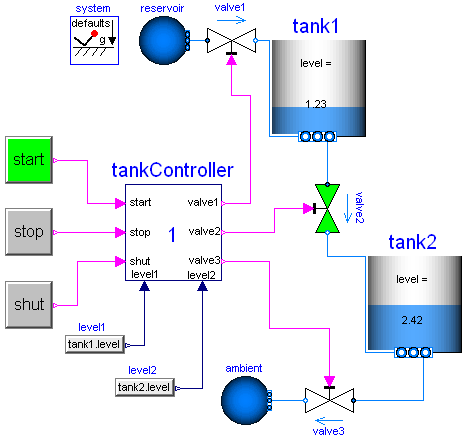
In the following figure the top level of the model is shown. This model is available from here.
In the right part of the figure, two tanks are shown. At the top part, a large fluid source is present from which fluid can be filled in tank1 when valve1 is open. Tank1 can be emptied via valve2 that is located in the bottom of tank2 and fills a second tank2 which in turn is emptied via valve3. The actual levels of the tanks are measured and are provided as signals level1 and level2 to the tankController.
The tankController is controlled by three buttons, start, stop and shut (for shutdown) that are mutually exclusive. This means that whenever one button is pressed (i.e., its state is true) then the other two buttons are not pressed (i.e., their states are false). When button start is pressed, the "normal" operation to fill and to empty the two tanks is processed:
The above "normal" process can be influenced by the following buttons:
The implementation of the tankController is shown in the next figure:
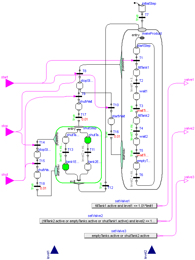
When the "start" button is pressed, the Modelica_StateGraph2 is within the Parallel step "makeProduct". During normal operation this step is not left.
When the "stop" button is pressed, the "makeProduct" step is at once terminated via the "suspend" port and the Modelica_StateGraph2 waits in step "stopStep1" for further commands. When the "start" button is pressed, the makeProduct step is re-entered via its resume port and the "normal" operation continues at the state where it was aborted by the suspend transition. If the "shut" button is pressed, the Modelica_StateGraph2 waits in the "shutStep" parallel step, until both tanks are empty and then waits at the "startStep" for further input.
The opening and closing of valves is not directly defined in the Modelica_StateGraph2. Instead via the "setValveX" components, the Boolean state of the valves are computed. For example, the output y of "setValve3" is computed as:
y = emptyTanks.active or shutTank2.active
i.e., valve3 is open, when step "emptyTanks" or when step "shutTank2" is active. Otherwise, valve3 is closed.
An alternative implementation of the tank controller is available from here. The differences to the implementation shown above are:
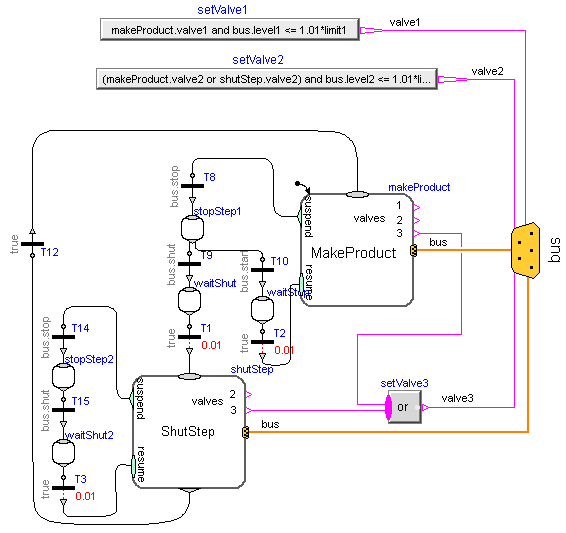
The top level of this alternative implementation of the tank controller is shown in the following figure:
The "MakeProduct" Parallel component is the initial step and performs the "normal" operation. When the "stop" button is pressed, the suspend transition T8 fires, the "MakeProduct" step is suspended and the graph goes in to step "stopStep1". Note, the transition condition of T8 is "bus.stop", i.e., this transition fires when variable stop from the bus is true. When "start" is pressed again, the "MakeProduct" step is resumed at the place where it was suspended. When "shut" is pressed, the Parallel component "ShutStep" is entered to shut down the tank system. Here it is still possible to press the "stop" button and then again continue with "shut".