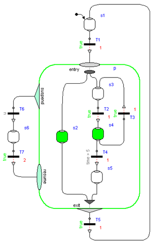
Subgraphs can be aggregated into superstates by using the Parallel component. This component acts both as a composite step (having just one branch) and as a Step that has parallel branches that are executed in parallel to each other. The Parallel component allows the user to place any StateGraph2 element inside it, especially Steps, Transitions, and Parallel components. In the following Figure, a typical Parallel component "p" is shown:
Here, the branch from "Step3" to "Step5" is executed in parallel to "Step2". A Transition connected to the output of a parallel branch component can only fire if the final Steps of the branches, that are connected to the "exit" port of the Parallel component, are active simultaneously. So, in the Figure above, the Parallel component is left, once Step2 and Step5 are active for one second, since then transition T5 fires.
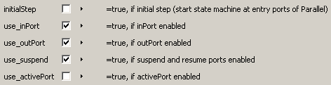
By default, a Parallel component does not have any outside ports. To achieve the StateGraph2 above, parameters use_inPort, use_outPort, and use_suspend have to be set to true, see next Figure:
A Parallel component has always an entry port, see Figure above, and it may have optionally an exit port. All branches in a Parallel Component must start at the entry port and at least one must terminate at the exit port, provided the exit port is enabled via parameter use_outPort. If a Parallel component shall be entered from the outside via a Transition, parameter use_inPort must be set to true, to enable an input port. If a Parallel Component shall be left via a transition to an outside step, parameter use_outPort must be set to true, to enable the output and the exit port. A Parallel component may be used as initial step, by setting parameter initialStep to true. All branches in a Parallel component may be running autonomously in parallel, by setting use_inPort=false, use_outPort=false, initialStep=true.
A Parallel component may be suspended and sub-sequently resumed. In the Figure above, Transition T6 fires whenever the input signal "u" is true, suspending the Parallel component "p" and the enclosed Steps s2, s3, s4 and s5 for two seconds. When Transition T7 fires, p is re-activated in the same states as when it was suspended (i.e., the same Steps become active, that have been active when the Parallel component was suspended).
Parallel and Step components have vectors of connectors. The dimensions of these vectors are set automatically in the corresponding parameter menu when performing a connection due to the "connectorSizing" annotation (a connection is connected to the next free element of a vectors of connectors when drawing the connection and the new vector dimension is set automatically as a modifier, if the dimension needs to be enlarged). If several Transitions could fire, the Transition that is connected to the lowest index of a vector of connectors really fires (so the firing priority is defined with the connection index). If transitions connected to the outPort and to the suspend port could fire at the same time instant, the transition connected to the outPort has higher priority and really fires.
As mentioned above, inPorts and outPorts of a Parallel component are optional and can be set by the user. If the parallel component has an inPort, then the entry port constitutes the connection between the Transition connected to the inPort and the first Steps to be activated in the Parallel component. If the Parallel component is configured to have an outPort, an exit port shows up on the bottom of the Parallel component, see above Figure. The Parallel component allows the entry port to branch out into several parallel paths. These branches are not allowed to interact. When all Steps connected to the exit port are active, the Parallel component is said to be available and may exit when the Transition connected to the outPort fires. In the Figure above Transition T5 fires when both Step s2 and s5 have been active together for one second and thereby deactivates the Parallel component p. Note, not all branches need to be connected to the exit port, if it is enabled.
The state of a Parallel component is available via the output variable active that can be used in action blocks (e.g. "parallel.active"). Alternatively, via parameter "use_activePort" the Boolean output port "activePort" can be enabled. When the Parallel component is active, activePort = true, otherwise it is false. This port can be connected to Boolean action blocks, e.g., from Modelica_StateGraph2.Blocks.MathBoolean.
No component contained within the Parallel component may be connected to any other component "outside" of the Parallel component, otherwise a translation error occurs. This rule is used to protect the user from making mistakes that could lead to unexpected results and states of the graph that are not well-defined.
In order to graphically organize large graphs in different levels of hierarchy and with encapsulation of variables, use component PartialParallel instead of Parallel.