
modelDraftTube
Model of a draft tube for reaction turbines

Extends from OpenHPL.Icons.DraftTube (Draft tube icon), Types.FrictionSpec (Reusable friction specification with multiple input methods), OpenHPL.Interfaces.TwoContacts (Model of two connectors).
Information
Two draft tube variants are modeled using momentum balance.
Parameterization:
- Conical diffuser: use
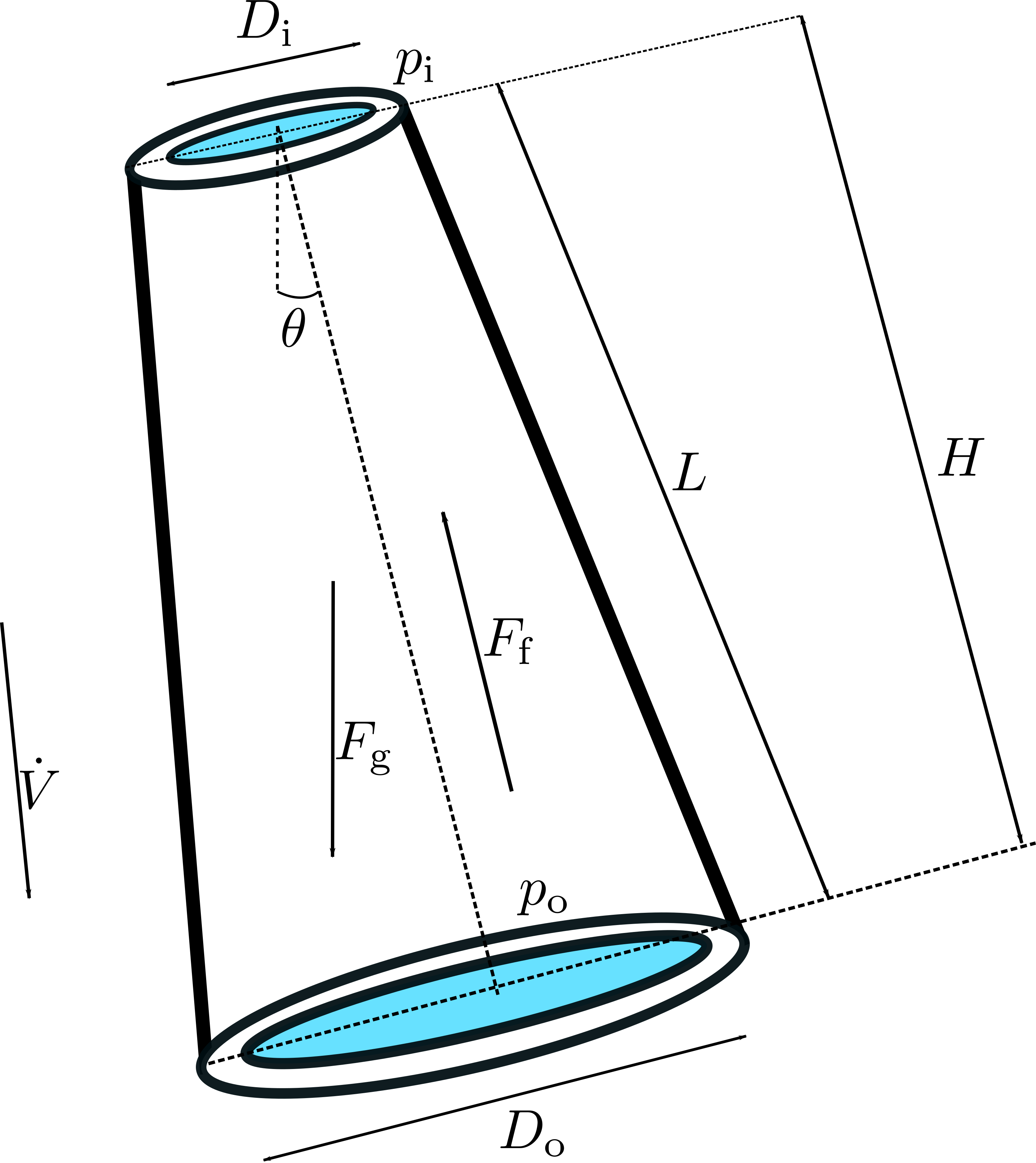
H,L,D_i, andD_o. The inclination is derived internally from the slope ratioH/L. - Moody spreading pipe: use
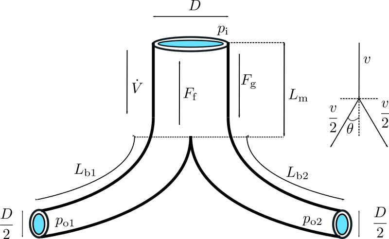
L_m,L_b,D_i,D_o, andtheta_moody.
They are:
- Conical diffuser: It is the most well-know draft tube which has efficiency of around 90% and mostly used for low head reaction turbines.
- Moody spreading draft tubes: When conical diffuser length exceeds beyond its stability for high head reaction turbines, either a elbow type draft tube is used which has around 70% of efficiency. However, other choice is to use Moody spreading draft tube that has efficiency of around 80%. The construction and design of Moody spreading draft tube is daunting and time consuming but it is mostly chosen for handling water whril at turbine's outlet.
The conical diffuser and Moody spreading draft tubes are shown below:
Parameters
| Type | Name | Default | Description |
|---|---|---|---|
| Friction | |||
| Types.FrictionMethod | FrictionMethod (from FrictionSpec) | data.FrictionMethod | Method for specifying pipe friction |
| SI.Height | p_eps_input (from FrictionSpec) | data.p_eps | Pipe roughness height (absolute) |
| Real | f_moody (from FrictionSpec) | data.f_moody | Moody friction factor (dimensionless, typically 0.01-0.05) |
| Real | m_manning (from FrictionSpec) | data.m_manning | Manning M (Strickler) coefficient M=1/n (typically 60-110 for steel, 30-60 for rock tunnels) |
| Boolean | use_n (from FrictionSpec) | data.use_n | If true, use Mannings coefficient n (=1/M) instead of Manning's M (Strickler) |
| Real | n_manning (from FrictionSpec) | data.n_manning | Manning's n coefficient (typically 0.009-0.017 for steel/concrete, 0.017-0.030 for rock tunnels) |
| SI.Diameter | D_h (from FrictionSpec) | Hydraulic diameter used for friction conversion | |
| Draft tube types | |||
| Types.DraftTube | DraftTubeType | OpenHPL.Types.DraftTube.ConicalDiffuser | Types of draft tube |
| Geometry | |||
| SI.Length | H | 7 | Vertical drop from inlet to outlet (conical diffuser) |
| SI.Length | L | 7.017 | Centerline/slant length (conical diffuser). Inclination is derived from H and L. |
| SI.Diameter | D_i | 4 | Diameter of the inlet side |
| SI.Diameter | D_o | 4.978 | Diameter of the outlet side |
| SI.Length | L_m | 4 | Length of main section (Moody spreading pipe) |
| SI.Length | L_b | 3 | Length of branch section (Moody spreading pipe) |
| Integer | theta_moody | 30 | Branch angle in deg for Moody spreading pipe |
| Initialization | |||
| Boolean | SteadyState | data.SteadyState | If true, starts in steady state |
| SI.VolumeFlowRate | Vdot_0 | data.Vdot_0 | Initial volume flow rate |
Connectors
| Type | Name | Default | Description |
|---|---|---|---|
| Contact_i | i (from TwoContacts) | Inlet contact (positive design flow direction is from i to o) | |
| Contact_o | o (from TwoContacts) | Outlet contact (positive design flow direction is from i to o) |
Components
| Type | Name | Default | Description |
|---|---|---|---|
| Data | data | Using standard data set | |
| SI.Diameter | D_ | 0.5*(D_i + D_o) | Average diameter |
| SI.Area | A_i | D_i^2*pi/4 | Inlet cross-section area of draft tube |
| SI.Area | A_o | D_o^2*pi/4 | Outlet cross-section area of draft tube |
| SI.Area | A_ | D_^2*pi/4 | Average cross-section area of conical diffuser |
| SI.Mass | m | Mass of water inside conical diffuser | |
| SI.Mass | m_m | Mass of water inside Main section Moody spreading pipes | |
| SI.Mass | m_b | Mass of water inside Branch section Moody spreading pipes | |
| SI.MassFlowRate | mdot_m | Mass flow rate inside Main section of Moody spreading pipes | |
| SI.MassFlowRate | mdot_b | Mass flow rate inside Branch section of Moody spreading pipes | |
| SI.Volume | V | Volume of water inside the draft tube | |
| SI.Momentum | M | Momentum of water inside the draft tube | |
| SI.Force | Mdot | Rate of change of water momentum | |
| SI.Force | F | Total force acting in the tube | |
| SI.Force | F_p | Pressure force | |
| SI.Force | F_f | Fluid frictional force | |
| SI.Force | F_g | Weight of water | |
| SI.Force | F_fm | Fluid frictional force in the Main section of Moody spreading pipe | |
| SI.Force | F_fb | Fluid frictional force in the Branch section of Moody spreading pipe | |
| SI.Velocity | v | Water velocity for conical diffuser | |
| SI.Velocity | v_m | Water velocity inside Main section of Moody spreading pipes | |
| SI.Velocity | v_b | Water velocity inside Branch section of Moody spreading pipes | |
| SI.Pressure | p_i | Inlet pressure | |
| SI.Pressure | p_o | Outlet pressure | |
| SI.Pressure | dp | p_o - p_i | Pressure drop in and out of draft tube |
| SI.MassFlowRate | mdot | Mass flow rate | |
| Real | phi_d | Generalized friction factor for draft tube | |
| Real | phi_d_o | Initial generalized friction factor for Moody spreading pipes | |
| SI.VolumeFlowRate | Vdot | Volume flow rate | |
| SI.VolumeFlowRate | Vdot_b | Volume flow rate for Branch section of Moody spreading pipes | |
| Real | cos_theta | H/L | Slope ratio for conical diffuser |
| Real | cos_theta_moody | cos(Modelica.Units.Conversions.from_deg(theta_moody)) | Calculating cos_theta_moody |
| Real | cos_theta_moody_by_2 | cos(Modelica.Units.Conversions.from_deg(theta_moody/2)) | Calculating cos_theta_moody_by_2 |