
modelPenstock

Extends from Modelica.Icons.ObsoleteModel (Icon for classes that are obsolete and will be removed in later versions), OpenHPL.Icons.Pipe (Pipe icon), OpenHPL.Interfaces.TwoContacts (Model of two connectors).
Information
This is a more detaied model of the pipe that can be use for proper modeling of penstock. (This model does not work well. Instead PenstockKP model can be used.)
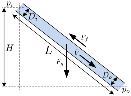
The model for the penstock with the elastic walls and compressible water with simple discretization method (Staggered grid). The geometry of the penstock is described due to figure:
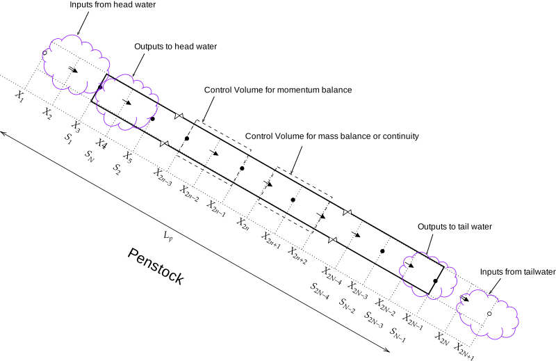
Conservation laws are usually solved by Finite-volume methods. With the Finite volume method, we divide the grid into small control volumes or control cells and then apply the conservation laws. The discretization method is based on Staggered grid scheme, where the penstock is divided in N segments, with input and output pressure as a boundary conditions. Can be describe as the follow figure:
Parameters
| Type | Name | Default | Description |
|---|---|---|---|
| Icon | |||
| Boolean | slanted (from Pipe) | false | Display slanted icon instead |
| Geometry | |||
| SI.Height | H | 420 | Height over which water fall in the pipe, m |
| SI.Length | L | 600 | length of the pipe, m |
| SI.Diameter | D_i | 3.3 | Diametr from the input side of the pipe |
| SI.Diameter | D_o | D_i | Diametr from the output side of the pipe |
| Initialization | |||
| SI.VolumeFlowRate | Vdot_0 | 20 | Initial volume flow rate |
| Discretization | |||
| Integer | N | 20 | Number of segments |
Connectors
| Type | Name | Default | Description |
|---|---|---|---|
| Contact_i | i (from TwoContacts) | Inlet contact (positive design flow direction is from i to o) | |
| Contact_o | o (from TwoContacts) | Outlet contact (positive design flow direction is from i to o) |
Components
| Type | Name | Default | Description |
|---|---|---|---|
| Data | data | Using standard data set | |
| SI.Diameter | dD | 0.5*(D_i + D_o) | |
| SI.Diameter[N] | D | linspace(D_i + dD/2, D_o - dD/2, N) | |
| SI.Diameter[N + 1] | D_ | linspace(D_i, D_o, N + 1) | |
| SI.Area[N] | A | D.^2*pi/4 | |
| SI.Area[N + 1] | A_ | D_.^2*pi/4 | |
| SI.Area[N - 2] | A_m | ||
| SI.Area | A_m_end | ||
| SI.Area | A_m_first | ||
| SI.Pressure | p_i | ||
| SI.Pressure | p_o | ||
| SI.Pressure[N - 1] | p_ | ||
| SI.Pressure | dp | data.rho*data.g*H/N | |
| SI.Pressure[N - 2] | p_m | ||
| SI.Length | dx | L/N | |
| SI.Length[N - 2] | Per_m | ||
| SI.MassFlowRate | mdot_R | ||
| SI.MassFlowRate | mdot_V | ||
| SI.MassFlowRate[N - 2] | mdot | ||
| SI.MassFlowRate[N] | m_exp | ||
| Real[N - 1] | F_ap | ||
| Real[N - 2] | F_m | ||
| Real[N] | F_exp | ||
| Real[N - 2] | p_eps_m | ||
| Real[3,N - 2] | Ap_m | ||
| Real | F_m_end | ||
| Real | F_m_first | ||
| SI.Force[N - 2] | F_g | ||
| SI.Force[N - 2] | F_p | ||
| SI.Density[N - 2] | rho_m | ||
| SI.Density | rho_m_end | ||
| SI.Density | rho_m_first | ||
| SI.Velocity[N] | v_exp | ||
| SI.VolumeFlowRate[N - 2] | V_p_out | ||
| SI.VolumeFlowRate | V_p_out_end |