modelPenstockKP

Extends from OpenHPL.Icons.Pipe (Pipe icon), Types.FrictionSpec (Reusable friction specification with multiple input methods), OpenHPL.Interfaces.TwoContacts (Model of two connectors).
Information
Elastic Penstock with KP Method
Note: The older Penstock model using the Staggered Grid scheme
is now marked as obsolete. This PenstockKP model, which implements the more accurate and numerically stable
KP (Kurganov-Petrova) method, is the recommended choice for all elastic penstock modeling.
This is a detailed model for the pipe that can be used for proper modelling of the penstock or other conduits. Unlike simple conduits, the penstock has considerable pressure variations due to substantial height drop. To make the model more realistic, compressible water and elastic walls are taken into account.
Compressibility
The isothermal compressibility βT relates density and pressure:
$$ \rho \approx \rho^\mathrm{atm}(1 + \beta_T(p - p^\mathrm{atm})) $$
Similarly for pipe cross-section area due to elastic walls:
$$ A \approx A^\mathrm{atm}(1 + \beta^\mathrm{eq}(p - p^\mathrm{atm})) $$
The total compressibility βtot = βT + βeq is related to the speed of sound
in water inside the pipe. The parameter PipeElasticity controls whether elastic walls are included.
PDE Formulation and KP Discretization
The model includes elastic walls and compressible water using the Kurganov-Petrova central upwind scheme (KP). Using the compressibility relationships, the ODEs for mass and momentum balances develop into PDEs:
$$ \frac{\partial U}{\partial t} + \frac{\partial F}{\partial x} = S $$
where \(U = [p_\mathrm{p}, \dot{m}_\mathrm{p}]^T\) is the state vector containing pressure and mass flow rate.
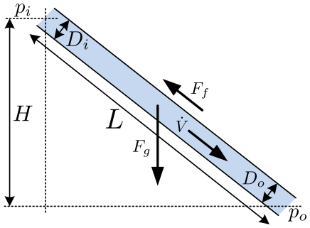
Figure: Geometry of the penstock model.
Conservation laws are solved by finite-volume methods. The pipe is divided into N segments,
with inlet and outlet pressures as boundary conditions. The given cell is denoted by j (the jth cell).
Cell averages are calculated at the center of the cell, and U denotes the average values of the conserved variables.
The left and right interfaces are denoted by j-1/2 and j+1/2 respectively.
At each cell interface, the right(+)/left(-) point values are reconstructed.
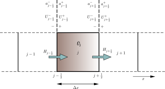
Figure: Discretization scheme showing cell j with interfaces and reconstruction points.
To determine the fluxes at the cell interface and the source term S, the KP scheme is used,
which is a second-order scheme that is well-balanced.

Implementation
The PenstockKP model uses the KP07.KPmethod function to discretize PDEs into ODEs.
The eigenvalues λ1,2 determine the wave propagation speeds and are related to the speed of sound
c = √(Ap/(Apatm ρatm βtot)).
Parameters
User specifies:
- Geometry: length
L, height differenceH, inlet/outlet diametersD_i/D_o, roughnessp_eps - Discretization: number of cells
N - Model fidelity:
PipeElasticitycheckbox to enable/disable elastic walls - Initialization: flow rate
Vdot_0and pressurep_p0vectors, orSteadyStateflag
More Information
More info about the KP penstock model can be found in [Vytvytskyi2017] and [Vytvytskyi2019].
Parameters
| Type | Name | Default | Description |
|---|---|---|---|
| Icon | |||
| Boolean | slanted (from Pipe) | false | Display slanted icon instead |
| Friction | |||
| Types.FrictionMethod | FrictionMethod (from FrictionSpec) | data.FrictionMethod | Method for specifying pipe friction |
| SI.Height | p_eps_input (from FrictionSpec) | data.p_eps | Pipe roughness height (absolute) |
| Real | f_moody (from FrictionSpec) | data.f_moody | Moody friction factor (dimensionless, typically 0.01-0.05) |
| Real | m_manning (from FrictionSpec) | data.m_manning | Manning M (Strickler) coefficient M=1/n (typically 60-110 for steel, 30-60 for rock tunnels) |
| Boolean | use_n (from FrictionSpec) | data.use_n | If true, use Mannings coefficient n (=1/M) instead of Manning's M (Strickler) |
| Real | n_manning (from FrictionSpec) | data.n_manning | Manning's n coefficient (typically 0.009-0.017 for steel/concrete, 0.017-0.030 for rock tunnels) |
| SI.Diameter | D_h (from FrictionSpec) | Hydraulic diameter used for friction conversion | |
| Geometry | |||
| SI.Height | H | 420 | Height difference from the inlet to the outlet of the pipe |
| SI.Length | L | 600 | length of the pipe |
| SI.Diameter | D_i | 3.3 | Diametr from the inlet side of the pipe |
| SI.Diameter | D_o | D_i | Diametr from the outlet side of the pipe |
| Initialization | |||
| Boolean | SteadyState | data.SteadyState | If true, starts in steady state |
| SI.VolumeFlowRate[N] | Vdot_0 | data.Vdot_0*ones(N) | Initial flow rate in the pipe vector |
| SI.Height | h_s0 | 69 | Initial water head before the pipe, m |
| SI.Pressure[N] | p_p0 | 1.013e5 + 997*9.81*(h_s0 + H/N/2):997*9.81*H/N:1.013e5 + 997*9.81*(h_s0 + H/N*(N - 1/2)) | Initial presure vector, bar |
| Discretization | |||
| Integer | N | 10 | Number of segments |
| Properties | |||
| Boolean | PipeElasticity | true | if checked - include pipe elasticity to the model |
Connectors
| Type | Name | Default | Description |
|---|---|---|---|
| Contact_i | i (from TwoContacts) | Inlet contact (positive design flow direction is from i to o) | |
| Contact_o | o (from TwoContacts) | Outlet contact (positive design flow direction is from i to o) |
Components
| Type | Name | Default | Description |
|---|---|---|---|
| OpenHPL.Data | data | Using standard data set | |
| SI.Diameter | dD | (D_i - D_o)/N | step in diameter change |
| SI.Diameter[N] | D | linspace(D_i + dD/2, D_o - dD/2, N) | centered diameter vector in atm. p. |
| SI.Diameter[N + 1] | D_ | linspace(D_i, D_o, N + 1) | boundary diameter vector in atm. p. |
| SI.Area[N] | A_atm | D.*D*pi/4 | centered cross are vector in atm. p. |
| SI.Area[N + 1] | A_atm_ | D_.*D_*pi/4 | boundary cross are vector in atm. p. |
| SI.Area[N] | A | centered cross are vector | |
| SI.Area[N,4] | A_ | boundary cross are vector | |
| SI.Area[N,4] | _A_atm | boundary cross are matrix in atm. p. | |
| SI.Pressure[N] | p_p | centered pressure | |
| SI.Pressure | dp | data.rho*data.g*H/N | initial p. step |
| SI.Pressure | p_i | Inlet pressure (LHS) | |
| SI.Pressure | p_o | Outlet Pressure (RHS) | |
| SI.Pressure[N,4] | p_ | boundary p. matrix | |
| SI.Length | dx | L/N | length step |
| SI.Length | dh | H/N | height step |
| SI.MassFlowRate[N] | mdot | centered mass flow | |
| SI.MassFlowRate | mdot_R | left bound mdot | |
| SI.MassFlowRate | mdot_V | right bound mdot | |
| SI.MassFlowRate[N,4] | mdot_ | boundary mdot matrix | |
| Real[2*N] | U | centered states | |
| Real[8,N] | U_ | boundary states | |
| Real[N] | F_ap | centered A*rho | |
| Real[N,4] | F_ap_ | bounddary A*rho | |
| Real[2*N] | S_ | source term | |
| Real[2*N,4] | F_ | F matrix | |
| Real[N,4] | lam1 | eigenvalue '+' | |
| Real[N,4] | lam2 | eigenvalue '-' | |
| SI.Density[N] | rho | centered density | |
| SI.Density[N,4] | rho_ | boundary density | |
| SI.Velocity[N,4] | v_ | bounds velocity | |
| SI.Velocity[N] | v | centered velocity | |
| SI.VolumeFlowRate[N] | Vdot | centered volumetric flow | |
| SI.Force[N] | F_f | centered friction force vector | |
| Real | theta | 1.3 | parameter for slope limiter |
| Functions.KP07.KPmethod | KP |