modelREECCU1
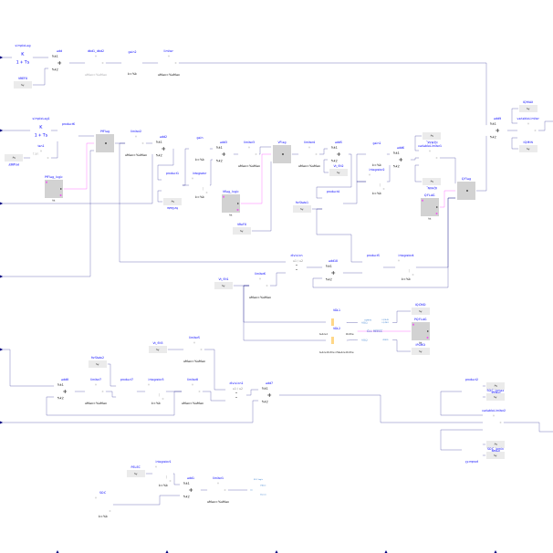
Extends from OpenIPSL.Electrical.Renewables.PSSE.ElectricalController.BaseClasses.BaseREECC (Base renewable energy electrical controller model C).
Information
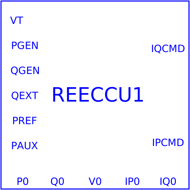
The REECCU1 component is an augmented version of the existing renewable energy electrical control (REECA1) model, and can be utilized to represent both type 3 and type 4 wind turbine electrical controllers as well as photovoltaic electrical controllers. The REECCU1 component can be connected to the plant controller (REPCA1). This electrical controller provides real (Ipcmd) and reactive (Iqcmd) current commands to the REGCA1 component, which are the outputs of this component.
For initialization purposes, there are 5 inputs that are derived from the inverter component: initial real and reactive injection currents (IP0 and IQ0), initial terminal voltage (v_0), and initial active and reactive power injections (p_0 and q_0).
In terms of connectivity with other components to form the renewable source, the REECCU1 component has six inputs, three of which are connected to the inverter component (for instance REGCA1), two more that can either be constant values from the power flow initialization or come from the connection to the plant controller, and an auxiliary input variable that is rarely used (usually constant and zero). The three REECCU1 inputs that take in values from the output of the inverter model are Vt, Pgen, and Qgen while the two inputs that could potentially be constant valued or come from the plant controller are Pref, and Qext.
The modelling of such devices is based, mainly, on the following references:
- Siemens: "PSS®E Model Library" [PSSE-MODELS],
- WECC: "Battery Storage Dynamic Modeling Guideline" [WECCBattery].
Parameters
| Type | Name | Default | Description |
|---|---|---|---|
| OpenIPSL.Types.PerUnit | Vdip | -99 | Low voltage threshold to activate reactive current injection logic (0.85 - 0.9) |
| OpenIPSL.Types.PerUnit | Vup | 99 | Voltage above which reactive current injection logic is activated (>1.1) |
| OpenIPSL.Types.Time | Trv | 0.01 | Filter time constant for voltage measurement (0.01 - 0.02) |
| OpenIPSL.Types.PerUnit | dbd1 | 0 | Voltage error dead band lower threshold (-0.1 - 0) |
| OpenIPSL.Types.PerUnit | dbd2 | 0 | Voltage error dead band upper threshold (0 - 0.1) |
| Real | Kqv | 0 | Reactive current injection gain during over and undervoltage conditions (0 - 10) |
| OpenIPSL.Types.PerUnit | Iqh1 | 1 | Upper limit on reactive current injection Iqinj (1 - 1.1) |
| OpenIPSL.Types.PerUnit | Iql1 | -1 | Lower limit on reactive current injection Iqinj (-1.1 - 1) |
| OpenIPSL.Types.PerUnit | vref0 | 1 | User defined voltage reference (0.95 - 1.05) |
| OpenIPSL.Types.Time | Tp | 0.01 | Filter time constant for electrical power (0.01 - 0.1) |
| OpenIPSL.Types.PerUnit | Qmax | 1 | Upper limits of the limit for reactive power regulator (0.4 - 1.0) |
| OpenIPSL.Types.PerUnit | Qmin | -1 | Lower limits of the limit for reactive power regulator (-1.0 - -0.4) |
| OpenIPSL.Types.PerUnit | Vmax | 1.1 | Maximum limit for voltage control (1.05 - 1.1) |
| OpenIPSL.Types.PerUnit | Vmin | 0.9 | Lower limits of input signals (0.9 - 0.95) |
| Real | Kqp | 0 | Reactive power regulator proportional gain (No predefined range) |
| Real | Kqi | 0.1 | Reactive power regulator integral gain (No predefined range) |
| Real | Kvp | 0 | Voltage regulator proportional gain (No predefined range) |
| Real | Kvi | 40 | Voltage regulator integral gain (No predefined range) |
| OpenIPSL.Types.Time | Tiq | 0.01 | Time constant on lag delay (0.01 - 0.02) |
| Real | dPmax | 99 | Power reference maximum ramp rate (No predefined range) |
| Real | dPmin | -99 | Lower limits of input signals (No predefined range) |
| OpenIPSL.Types.PerUnit | Pmax | 1 | Maximum power limit |
| OpenIPSL.Types.PerUnit | Pmin | 0 | Minimum power limit |
| OpenIPSL.Types.PerUnit | Imax | 1.1 | Maximum limit on total converter current (1.1 - 1.3) |
| OpenIPSL.Types.Time | Tpord | 0.02 | Power filter time constant (0.01 - 0.02) |
| OpenIPSL.Types.PerUnit | Vq1 | 0.2 | Reactive Power V-I pair, voltage (user defined) |
| OpenIPSL.Types.PerUnit | Iq1 | 0.75 | Reactive Power V-I pair, current (user defined) |
| OpenIPSL.Types.PerUnit | Vq2 | 0.5 | Reactive Power V-I pair, voltage (user defined) |
| OpenIPSL.Types.PerUnit | Iq2 | 0.75 | Reactive Power V-I pair, current (user defined) |
| OpenIPSL.Types.PerUnit | Vq3 | 0.75 | Reactive Power V-I pair, voltage (user defined) |
| OpenIPSL.Types.PerUnit | Iq3 | 0.75 | Reactive Power V-I pair, current (user defined) |
| OpenIPSL.Types.PerUnit | Vq4 | 1 | Reactive Power V-I pair, voltage (user defined) |
| OpenIPSL.Types.PerUnit | Iq4 | 0.75 | Reactive Power V-I pair, current (user defined) |
| OpenIPSL.Types.PerUnit | Vp1 | 0.2 | Real Power V-I pair, voltage (user defined) |
| OpenIPSL.Types.PerUnit | Ip1 | 1.11 | Real Power V-I pair, current (user defined) |
| OpenIPSL.Types.PerUnit | Vp2 | 0.5 | Real Power V-I pair, voltage (user defined) |
| OpenIPSL.Types.PerUnit | Ip2 | 1.11 | Real Power V-I pair, current (user defined) |
| OpenIPSL.Types.PerUnit | Vp3 | 0.75 | Real Power V-I pair, voltage (user defined) |
| OpenIPSL.Types.PerUnit | Ip3 | 1.11 | Real Power V-I pair, current (user defined) |
| OpenIPSL.Types.PerUnit | Vp4 | 1 | Real Power V-I pair, voltage (user defined) |
| OpenIPSL.Types.PerUnit | Ip4 | 1.11 | Real Power V-I pair, current (user defined) |
| Modelica.Units.SI.Time | T | 999 | Battery discharge time |
| OpenIPSL.Types.PerUnit | SOCini | 0.5 | Initial state of charge |
| OpenIPSL.Types.PerUnit | SOCmax | 0.8 | Maximum allowable state of charge |
| OpenIPSL.Types.PerUnit | SOCmin | 0.2 | Minimum allowable state of charge |
| Control | |||
| Boolean | pfflag (from BaseREECC) | true | Constant output value |
| Boolean | vflag (from BaseREECC) | true | Constant output value |
| Boolean | qflag (from BaseREECC) | true | Constant output value |
| Boolean | pqflag (from BaseREECC) | true | Constant output value |