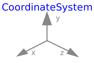
modelCoordinateSystem
Information
Note: This element is intended to be used in PlanarWorld and its derivatives only! To visualize a coordinate system in your model, the best solution is usually to use the visualizer Advanced.CoordinateSystem. The only difference between this two visualizers is that the current one does not utilizes outer planarWorld, whereas the other does.
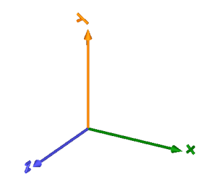
This element enables visualization of an orthogonal coordinate system as shown in the following picture.
The variables r, R and r_shape
are declared as (time varying) input variables.
If the default equation is not appropriate, a corresponding
modifier equation has to be provided in the
model where a CoordinateSystem instance is used, e.g., in the form
PlanarMechanics.Visualizers.Advanced.CoordinateSystem coordinateSystem(r = {sin(time), 0, 0.3});
Color of each axis can be set individually using a RGB color space given in the range 0 .. 255. Predefined colors from Types.Defaults are used throughout the library to get a coherent visualization.
Parameters
| Type | Name | Default | Description |
|---|---|---|---|
| SI.Length | axisLength | 0.5 | Length of world axes arrows |
| SI.Diameter | axisDiameter | axisLength/40 | Diameter of world axes arrows |
| MB.Types.Color | color_x | PlanarMechanics.Types.Defaults.FrameColor | Color of x-arrow |
| MB.Types.Color | color_y | color_x | Color of y-arrow |
| MB.Types.Color | color_z | color_x | Color of z-arrow |
| Axes labels | |||
| Boolean | axisShowLabels | true | True, if labels shall be shown |
| SI.Length | labelStart | 1.05*axisLength | |
| SI.Length | scaledLabel | PlanarMechanics.Types.Defaults.FrameLabelHeightFraction*axisDiameter | |
Components
| Type | Name | Default | Description |
|---|---|---|---|
| SI.Position[3] | r | {0, 0, 0} | Position vector from origin of world frame to origin of object frame, resolved in world frame |
| MB.Frames.Orientation | R | MB.Frames.nullRotation() | Orientation object to rotate the world frame into the object frame |
| SI.Position[3] | r_shape | {0, 0, 0} | Position vector from origin of object frame to shape origin, resolved in object frame |