
modelTestCase2
Test Case 2, Section 5.2, focuses on the dynamic behavior of the model for the synchronous generator and its governor
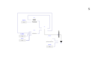
Extends from Modelica.Icons.Example (Icon for runnable examples).
Components
| Type | Name | Default | Description |
|---|---|---|---|
| PowerGrids.Electrical.System | systemPowerGrids | ||
| PowerGrids.Electrical.Machines.SynchronousMachine4Windings | GEN | ||
| PowerGrids.Electrical.Buses.ReferenceBus | NGEN | ||
| PowerGrids.Electrical.Controls.TurbineGovernors.IEEE_TGOV1 | TGOV | ||
| PowerGrids.Electrical.Controls.ExcitationSystems.IEEE_AC4A | AVR | ||
| Modelica.Blocks.Sources.RealExpression | zero | ||
| Modelica.Blocks.Sources.RealExpression | VrefPu | ||
| Modelica.Blocks.Sources.RealExpression | RefLPu | ||
| PowerGrids.Electrical.Loads.LoadImpedancePQInputs | LOAD | ||
| Modelica.Blocks.Sources.Step | PLoad | ||
| Modelica.Blocks.Sources.RealExpression | zero2 | ||
| Types.PerUnit | AA_01_GEN_UPu | GEN.port.VPu | Fig. 5-3, terminal voltage |
| Types.PerUnit | AA_02_GEN_PPu | GEN.port.PGenPu | Fig. 5-4, active power of the synchronous machine |
| Types.PerUnit | AA_03_GEN_PmechPu | GEN.PmPu | Fig. 5-5, mechanical power of the synchronous machine |
| Types.PerUnit | AA_04_GEN_omegaPu | GEN.omegaPu | Fig. 5-6, speed |