
modelTestCase3
Test Case 3, Section 5.3, focuses on the dynamic behavior of the model for the synchronous machine with its whole control in response to a short-circuit
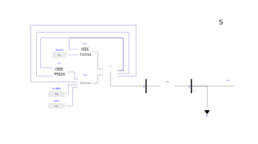
Extends from Modelica.Icons.Example (Icon for runnable examples).
Components
| Type | Name | Default | Description |
|---|---|---|---|
| PowerGrids.Electrical.System | systemPowerGrids | ||
| PowerGrids.Electrical.Machines.SynchronousMachine4Windings | GEN | ||
| PowerGrids.Electrical.Buses.Bus | NTLV | ||
| PowerGrids.Electrical.Buses.BusFault | NTHV | ||
| PowerGrids.Electrical.Branches.TransformerFixedRatio | TGEN | ||
| PowerGrids.Electrical.Controls.TurbineGovernors.IEEE_TGOV1 | TGOV | ||
| PowerGrids.Electrical.Controls.ExcitationSystems.IEEE_AC4A | AVR | ||
| PowerGrids.Electrical.Controls.PowerSystemStabilizers.IEEE_PSS2A | PSS | ||
| Modelica.Blocks.Sources.RealExpression | zero | ||
| Modelica.Blocks.Sources.RealExpression | VrefPu | ||
| Modelica.Blocks.Sources.RealExpression | RefLPu | ||
| PowerGrids.Electrical.Loads.LoadImpedancePQ | GRIDL | ||
| Electrical.Buses.EquivalentGrid | GRID | ||
| Types.PerUnit | AA_01_GEN_Upu | GEN.port.VPu | Fig. 5.7, terminal voltage |
| Types.PerUnit | AA_02_GEN_efd | GEN.ufPuIn | Fig. 5.8, excitation voltage |
| Types.PerUnit | AA_03_GEN_Ppu | GEN.port.PGenPu/0.95 | Fig. 5.9, active power of the synchronous machine |
| Types.PerUnit | AA_04_GEN_Qpu | GEN.port.QGenPu/0.314583 | Fig. 5.10, reactive power of the synchronous machine |
| Types.PerUnit | AA_05_GEN_omegapu | GEN.omegaPu | Fig. 5.11, speed |
| Types.PerUnit | AA_06_PSS_out | PSS.VstPu | Fig. 5.12, PSS output signal |
| Types.PerUnit | AA_07_GRIDL_Ppu | GRIDL.port.PPu/0.95 | Fig. 5.13, active power of the load |
| Types.PerUnit | AA_08_GRIDL_Qpu | GRIDL.port.QPu/0.1519 | Fig. 5.14, reactive power of the load |