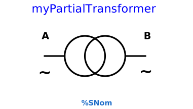
modelmyPartialTransformer

Partial model for transformers

Extends from Icons.myTransformer (Icon for transformer), Icons.myTwoPortsAC (Completing two ports AC icon).

Information

A transformer can be modeled as a dedicated Pi-network. A diagram of the model is shown in the figure.

The model describes a transformer with fixed transformer ratio with Ya=0, Yb=G+jB and k = UNomB/UNomA*exp(j*theta).

Parameters

TypeNameDefaultDescription
Types.myVoltageUNomAReference voltage at primary side
Types.myVoltageUNomBReference voltage at secondary side
Types.myAngletheta0Fixed phase shift
Types.myResistanceRSeries resistance at primary side
Types.myReactanceX0Series reactance at primary side
Types.myConductanceG0Shunt conductance at primary side
Types.mySusceptanceB0Shunt susceptance at primary side
Types.myApparentPowerMVASNom0Nominal power of the transformer. 0 means no control

Connectors

TypeNameDefaultDescription
Interfaces.myAcausalTerminalterminalATerminal A of the node
Interfaces.myAcausalTerminalterminalBTerminal B of the node

Components

TypeNameDefaultDescription
Types.myCurrentIACM.abs(terminalA.i)Current flowing port A
Types.myVoltageUAsqrt(3)*CM.abs(terminalA.v)Voltage at port A
Types.myCurrentIBCM.abs(terminalB.i)Current flowing port B
Types.myVoltageUBsqrt(3)*CM.abs(terminalB.v)Voltage at port B
Types.myApparentPowerSsqrt(3)*IA*UAApparent power flowing port A