modelmyLineWithFault
MV or LV line with constant impedance and fault at intermediate position
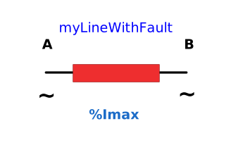
Extends from Icons.myLine (Icon for line), Icons.myTwoPortsAC (Completing two ports AC icon), Icons.myFault (Icon for fault).
Information
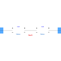
A line can be modeled as a dedicated Pi-network. A diagram of the model is shown in the next figure:

Parameters
| Type | Name | Default | Description |
|---|---|---|---|
| Types.myVoltage | UNom | Reference voltage of the line | |
| Types.myResistance | R | Series resistance of phase conductor | |
| Types.myReactance | X | 0 | Series reactance of phase conductor |
| Types.myConductance | G | 0 | Shunt conductance of phase conductor coupling |
| Types.mySusceptance | B | 0 | Shunt susceptance of phase conductor coupling |
| Types.myPerUnit | l | 1 | lineic coefficient |
| Types.myCurrent | Imax | 0 | Maximum admissible current. 0 means no control |
| Fault data | |||
| Types.myPerUnit | faultLocationPu | Location of the fault (0: port A, 1: port B) | |
| Types.myResistance | RFault | Fault resistance | |
| Types.myReactance | XFault | 0 | Fault reactance |
| Types.myTime | startTime | Start time of the fault | |
| Types.myTime | stopTime | End time of the fault | |
Connectors
| Type | Name | Default | Description |
|---|---|---|---|
| Interfaces.myAcausalTerminal | terminalA | Terminal A of the node | |
| Interfaces.myAcausalTerminal | terminalB | Terminal B of the node |
Components
| Type | Name | Default | Description |
|---|---|---|---|
| myLightLine | lineA | ||
| myLightLine | lineB | ||
| PartialModels.myFault | myFault | ||
| Types.myCurrent | IA | CM.abs(terminalA.i) | Current flowing port A |
| Types.myVoltage | UA | sqrt(3)*CM.abs(terminalA.v) | Voltage at port A |
| Types.myCurrent | IB | CM.abs(terminalB.i) | Current flowing port B |
| Types.myVoltage | UB | sqrt(3)*CM.abs(terminalB.v) | Voltage at port B |
| Types.myApparentPower | S | sqrt(3)*IA*UA | Apparent power flowing port A |