classRLink
Rotational Link
Extends from Modelica.Mechanics.MultiBody.Interfaces.PartialTwoFrames (Base model for components providing two frame connectors + outer world + assert to guarantee that the component is connected), Servomechanisms.Utilities.IconName.
Information
General
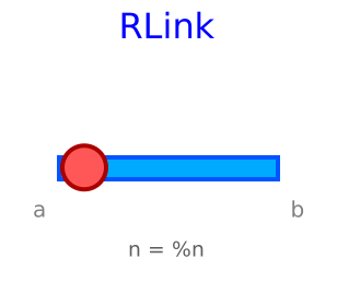
This is the model of a rotational link.
Implementation
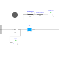
Using the component Link and Revolute Joint . The revolute joint uses:
useAxisFlange = trueto enable the mechanical rotational interface (for example a motor or a torque source).
Notes
- The user can modify parameters of the link.
- A fixed frame is added to visualize the frame_b of the link (although it can be placed in other location in the parameters).
- For some reason, in the diagraman view the connections with frame_a and frame_b are not visible.
- To use this element it is necessary to include a World component.
Example
RRParameters
| Type | Name | Default | Description |
|---|---|---|---|
| String | shape | "box" | shape of visualizer:"shape", "box", "cylinder" |
| Modelica.Mechanics.MultiBody.Types.Axis | n | {0, 0, 1} | Axis of rotation resolved in frame_a (= same as in frame_b) |
| if shape | |||
| SI.Position[3] | r | Vector from frame_a to frame_b resolved in frame_a | |
| SI.Position[3] | r_CM | Vector from frame_a to center of mass, resolved in frame_a | |
| SI.Mass | m | Mass of rigid body | |
| SI.Length | shapeLength | 1 | |
| SI.Distance | shapeWidth | boxLength/20 | |
| SI.Distance | shapeHeight | boxWidth | |
| String | shapeType | "modelica://Servomechanisms//Resources//b2.dxf" | Type of shape |
| Real | extra | 1 | Additional parameter depending on shapeType (see docu of Visualizers.Advanced.Shape) |
| if shape › Inertia tensor (resolved in center of mass, parallel to frame_a) | |||
| SI.Inertia | I_11 | 0.001 | (1,1) element of inertia tensor |
| SI.Inertia | I_22 | 0.001 | (2,2) element of inertia tensor |
| SI.Inertia | I_33 | 0.001 | (3,3) element of inertia tensor |
| SI.Inertia | I_21 | 0 | (2,1) element of inertia tensor |
| SI.Inertia | I_31 | 0 | (3,1) element of inertia tensor |
| SI.Inertia | I_32 | 0 | (3,2) element of inertia tensor |
| if box | |||
| SI.Length | boxLength | 1 | |
| SI.Distance | boxWidth | boxLength/20 | |
| SI.Distance | boxHeight | boxWidth | |
| if cylinder | |||
| SI.Length | cylinderLength | 1 | |
| SI.Distance | cylinderDiameter | cylinderLength/20 | |
| Parameters only for cylinder and box | |||
| SI.Density | density | 7700 | Density of link (e.g., steel: 7700 .. 7900, wood : 400 .. 800) |
| Frames | |||
| Real | frameFactor | 0.1 | ratio of frame respect world origin frame |
| SI.Position[3] | rFrame | {0, 0, 0} | |
Connectors
| Type | Name | Default | Description |
|---|---|---|---|
| Interfaces.Frame_a | frame_a (from PartialTwoFrames) | Coordinate system a fixed to the component with one cut-force and cut-torque | |
| Interfaces.Frame_b | frame_b (from PartialTwoFrames) | Coordinate system b fixed to the component with one cut-force and cut-torque | |
| Modelica.Mechanics.Rotational.Interfaces.Flange_a | flange_a |
Components
| Type | Name | Default | Description |
|---|---|---|---|
| Modelica.Mechanics.MultiBody.Joints.Revolute | revolute1 | ||
| Link | link | ||
| Modelica.Mechanics.MultiBody.Visualizers.FixedFrame | origin | ||
| Modelica.Mechanics.MultiBody.Parts.FixedRotation | fixedrotation1 | ||
| Modelica.Mechanics.MultiBody.Visualizers.FixedFrame | fixedframe1 | ||
| Modelica.Mechanics.MultiBody.Parts.FixedTranslation | fixedtranslation1 |