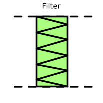
modelFilter

Information
This components models the mass flow rate through a filter from a pressure difference at boundaries and nominal sizing point. The flow regime is steady state.
The mathematical model under this component derives from the integrated Darcy law for a compressible fluid. In that law, the flow is supposed to linearly vary with the pressure difference. Knowing the pressure drop and the flow (m3/s) at an operating (or nominal) point, all the other working points can be guessed from the product of the ratio of the current pressure drop over the nominal pressure and the nominal volume flow rate.
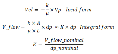
The mass flow rate relation derives:

Where:
-
dpis the boundary pressure difference between port_a.p and port_b.p -
kis the permeability -
μis the dynamic viscosity -
Ais inlet cross section -
Lis length of the sample units -
Kis a kind of linear the pressure loss coefficient (or hydraulic conductance) -
dis the upstream density -
m_flowis the mass flow rate induced by convection
Parameters
| Type | Name | Default | Description |
|---|---|---|---|
| Flow | |||
| Real | K | V_flow_nominal/dp_nominal | linear pressure loss coefficient |
| Nominal operating point | |||
| Modelica.SIunits.Pressure | dp_nominal | Nominal pressure drop | |
| Modelica.SIunits.VolumeFlowRate | V_flow_nominal | Nominal volume flowrate | |
Connectors
| Type | Name | Default | Description |
|---|---|---|---|
| Modelica.Fluid.Interfaces.FluidPort_a | port_a | ||
| Modelica.Fluid.Interfaces.FluidPort_b | port_b |
Components
| Type | Name | Default | Description |
|---|---|---|---|
| Modelica.SIunits.PressureDifference | dp | ||
| Modelica.SIunits.MassFlowRate | m_flow | Aperture flow kg/s | |
| Modelica.SIunits.Density | d |
Contents
| Name | Description |
|---|---|
 Medium Medium |