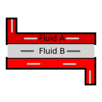
modelAnalyticWetExchanger

Information
This components allows to model heat and moisture laden transfers between a moist air media and a cooling fluid (commonly water). The mathematical model under this component takes inspiration from the paper: Methodologies d’identification d’économies d’energie : application aux systèmes de climatisation à eau glacee where the theoretical approach under the wet exchanger modelling is summarized here. The module embedes a modelling of a fully dry exchanger (variable with suffix '_1' ex:TA_out_1) and a model of a partially or fully wet (variable with suffix '_2' ex:TA_out_2). Both the fully dry exchange and the wet exchange are running simultaneously during the simulation. The output values are taken from one of the two configurations based on the value of the wet surface. A null or negative value means a fully dry exchange. To avoid chattering between the configurations, the outputs are computed by a polynomial interpolation close to zero value for the wet surface. For information regarding the dry exchange, please refer to the dry exchanger module. The following description focuses only on the wet exchange.
The physical model under this module uses the following assumptions:
- The lewis number is constant and equal to one
- The sensible term for the water vapour within the expression of the mixing specific enthalpy is neglected
- The conduction resistance within the tube between the moist air and the cooling fluid is neglected regarding the great thermal conductivity of used material. The heat regime is considered as quasistatic
- The exchanger is adiabatic regarding the environment
- The convective heat exchange coefficients between the tube and the cooling fluid and the moist air and the condensation film are constant
- The exchanger is linkened to an counter flow exchanger
To sum up the approach of a wet echange modlling described by the paper and the article above, The link between the mass and heat transfer is made via a Lewis number (Le) equal to one. It is discussed in the paper the relevancy of the assumptions of a Le = 1.

The founding principles of the representation method were established according to the work of [THRELKELD, 1970]. This method aggregates the phenomena of heat and mass transfer in an enthalpy exchange between air and water represented by a fictitious enthalpy.
Exchange between the moist air and the condensation film
It is assumed that the air immediately against the surface of the condensing film is saturated at the surface temperature of the condensing film. The water vapor and the condensation water being in equilibrium, the temperature of the condensation film is the temperature of the saturated air Tsat. The exchange between the air and the condensing film is expressed as follows:

In the temperature range [15 - 30°C] on which we are working, the term [cp T] represents only about 1% of the total enthalpy and can therefore be neglected. The enthalpy of humid air can then be written as follows:

By introducing the expression of the number of LEWIS, we obtain:

If we consider a number of LEWIS of 1 in the domain considered, the expression becomes:

It can be seen that, for the air / condensation film exchange, the two exchange potentials for temperature gradient and humidity gradient have been replaced by a single enthalpy potential.
Exchange between the condensation film and the cooling fluid
Regarding the exchange between the condensation film and the cooling fluid, the principle of representation is to be reduced to a homogeneous expression with that of the exchange between the air and the condensing film. We then assume that in a small temperature scale, we can represent the enthalpy of saturated air as a linear function of temperature:
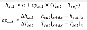
If the conduction in the tube and the condensing film is neglected due to the high conductivity of the materials used and of the water regarding the convective phenomena, the heat exchange between the condensing film and the water current expresses as follows:

Using the assumption that cpsat does not vary over the small temperature interval taken into account, water is then represented by a fictitious enthalpy corresponding to the enthalpy that saturated air would have at water temperature:

Considering the expression of the heat flow in the different exchanges, we then conceive of a direct exchange between air and temperature by introducing the expression of two resistors in series, one comprising the convective exchange between the air and the condensation film (Uext), the other comprising the conductive exchange (neglected) and the convective exchange between the tube and the water (Uint). The global conductance is therefore written, associating transfer conductance and exchange surface:

The heat and mass exchange within the cold battery is then described by the following expression of the power:

The whole of this approach therefore amounts to substituting for the two thermodynamic forces generating the heat flow, a single force derived from the enthalpy of humid air. It then becomes possible to apply the calculation techniques developed for heat exchangers using this unified expression of heat and mass transfer.
Methodology of the heat exchange coefficient calculation
As presented above, the value of the convective heat exchange coefficient hv_A and hv_B are required. However, their value are often not available in the manufacturer's data sheets. The only available data is sometimes the global heat exchange coefficient (K). The choice has been to have as parameter K and hv_A to computed hcv_B from K and hcv_A as follows. If the configuration flow is not counter flow, the coefficient K here has to be the coefficient that would have a counter flow exchanger with the same output properties.
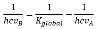
In exchanger dealing with air, it is common to used fins to increase the surface of exchange and thus the exchanged heat. The surface of exchange between the cooling fluid and the tube (piping) and between the pipe and the air is not the same. In that case, the supplier mainly refers the value of K to the largest surface (surface tube / air). With the above formula, the convective exchange coefficient hcv_B is not related to the exchange surface between the cooling fluid and the tube but to the exchange surface between the tube and the air (the largest surface ). In such way, the knowledge of the exchange surface between the cooling fluid and the tube is not required:

Parameters
| Type | Name | Default | Description |
|---|---|---|---|
| Real | phi_out | 0.8 | |
| SI.SpecificEnergy | Ll | 2501e3 | Latent heat of liquifaction at 0°C |
| SI.CoefficientOfHeatTransfer | hcv_B | (1/K_global - 1/hcv_A)^(-1) | |
| Geometrical parameters | |||
| SI.Area | CrossSectionA | 4.26 | Cross section of the pipe for the fluid A |
| SI.Area | CrossSectionB | 4.26 | Cross section of the pipe for the fluid B |
| SI.Area | ExchangeSurface | 0.0 | Largest exchange surface area |
| Flow parameters | |||
| Real | ksi_fixedA | 1.0 | |
| Real | ksi_fixedB | 1.0 | |
| Exchange parameters | |||
| SI.CoefficientOfHeatTransfer | K_global | Global heat transfer coeffcient | |
| SI.CoefficientOfHeatTransfer | hcv_A | Heat transfer coeffcient Wall<->Fluid A | |
Connectors
| Type | Name | Default | Description |
|---|---|---|---|
| Modelica.Fluid.Interfaces.FluidPort_a | port_in_A | ||
| Modelica.Fluid.Interfaces.FluidPort_b | port_out_A | ||
| Modelica.Fluid.Interfaces.FluidPort_a | port_in_B | ||
| Modelica.Fluid.Interfaces.FluidPort_b | port_out_B |
Components
| Type | Name | Default | Description |
|---|---|---|---|
| MediumA.ThermodynamicState | stateA_in | State of fluid A a inlet | |
| MediumB.ThermodynamicState | stateB_in | State of fluid B a inlet | |
| SI.SpecificHeatCapacity | cpA | ||
| SI.SpecificHeatCapacity | cpB | ||
| SI.MassFlowRate | m_flowA | Mass flow rate of fluid A | |
| SI.MassFlowRate | m_flowB | Mass flow rate of fluid B | |
| SI.ThermalConductance | QcA | Thermal flow rate unit | |
| SI.ThermalConductance | QcB | Thermal flow rate unit | |
| SI.Temperature | TA_in | ||
| SI.Temperature | TA_out | ||
| SI.Temperature | TB_in | ||
| SI.Temperature | TB_out | ||
| SI.Power | Pex | exchanged power | |
| Real | NTU_1 | Number of transfer unit | |
| Real | Cr_1 | Ration of thermal condutance | |
| SI.Efficiency | Eff_1 | Exchanger effectiveness | |
| SI.Temperature | TA_out_1 | ||
| SI.Temperature | TB_out_1 | ||
| SI.Power | Pex_1 | ||
| SI.Temperature | TA_mid_2 | ||
| SI.Temperature | TA_mid_buffer | ||
| SI.Temperature | TB_mid_2 | ||
| SI.Temperature | TB_out_2 | ||
| SI.Temperature | TA_out_2 | ||
| SI.Temperature | Tdew | ||
| SI.Temperature | Tsat_out | ||
| SI.Pressure | p_water | ||
| Real | NTU_2 | ||
| Real | NTU_wet | Number of transfer unit | |
| Real | Cr_wet | ||
| SI.Efficiency | Eff_2 | ||
| SI.Efficiency | Eff_wet | Exchanger effectiveness | |
| SI.Area | S_sensible | Sensible surface to achieved saturation on moist air | |
| SI.Area | S_wet | Sensible surface to achieved saturation on moist air | |
| SI.MassFraction | wsat_eq_in | ||
| SI.MassFraction | wA_in | ||
| SI.MassFraction | wsat_out | ||
| SI.MassFraction | wA_out_2 | ||
| SI.MassFraction | XA_out_2 | ||
| SI.MassFraction | wA_out | Moisture content peer kg of dry air | |
| SI.SpecificEnthalpy | hsat_eq_in | ||
| SI.SpecificEnthalpy | hA_mid_2 | ||
| SI.SpecificEnthalpy | hA_out_2 | ||
| SI.SpecificEnthalpy | hcond_out | ||
| SI.SpecificEnthalpy | hA_sat_in | Enthalpies peer kg of dry air | |
| SI.SpecificHeatCapacity | cp_eq | Specific heat capacity of the fictive fluid | |
| SI.MassFlowRate | m_flow_eq | Mass flow rate of the fictive fluid | |
| SI.Power | Q_flow_wet | ||
| SI.Power | Q_flow_dry | ||
| SI.Power | Q_flow_wet_2 | ||
| SI.Power | Q_flow_dry_2 | ||
| SI.Power | P_sensible | Sensible exchanged power | |
| SI.Power | P_latent | Latent exchanged power |
Contents
| Name | Description |
|---|---|
 MediumA MediumA | |
 MediumB MediumB |