
modelHeating
Information
Basic Idea of the model
This model describes a Building Heating System (BHS) of a dwelling based on a Electric Heat Pump (EHP) with a Heater Rod (HR) as auxiliary heater as heat source, and RoomHeating as heat sink. Key part of this model is a PID-controller and a power splitter. The basic block diagram is shown below.
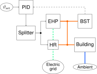
A PID controller controls the EHP+HR operating point based on a Buffer Storage Tank (BST) temperature set-point. The set-point is given by parameter. The Splitter splits the requested heat flow rate to the EHP and HR based on different ambient and system conditions. For more details, have a look at the Splitter model.
The parameters of the PID-Model were measured at a real EHP. The laboratory experiments were conducted at the SYSLAB at the Technical University of Denmark (DTU). Details of the project and the results can be found at: https://zenodo.org/records/17054821.
Control Bus - external control modes
The model is equiped with a expandable connector called ControlBus. Dependent on the ControlType, different control modes are possible, as described below.
- Internal: No external control. The internal PID controller is active an controls the BST temperature based on the parameter set value.
- Limit_P: Active power is limited from outside via
controlBus.P_limit. - External_P: The internal PID controller is bypassed and a P controller is active, controlling the consumed active power set by
controlBus.P_externalfrom the grid. In this operation mode, the HP and HR are active independent from the temperature set point. Useful for externally controlled components, like aggregators. - External_T: External temperature set-value
controlBus.T_buffer_offsetwill be used. The internal PID controller is still active.
controlBus.SignalActive is true. Otherwise, the internal PID controller is active as it is in the mode Internal. When controlBus.SignalActive changes, respective controllers are reinitialized.
Initialization
There are two possible initalization methods for this block, as defined in Modelica.Blocks.Types.Init
initType |
|
NoInit |
No initialization. States are zero |
SteadyState |
Initialization in steady state |
InitialState |
Not applicable |
InitialOutput |
Not applicable |
- NoInit: The system is initialized with states equal to zero. This is equivalent to a switched off system for simulation start. It can be useful to if the start of all components and controllers should be simulated.
- SteadyState: The system is initialized in steady state. All derivatives are zero, and the states are calculated accordingly.
Parameters
| Type | Name | Default | Description |
|---|---|---|---|
| String | tappingProfilePath | "" | |
| Boolean | useTappingCycles | true | |
| TransiEnt.Basics.Units.AirChangeRate | airChangeRate | 0.5 | |
| Modelica.Units.SI.SpecificHeatCapacity | cp_air | 1012 | |
| Modelica.Units.SI.Density | rho_air | 1.225 | |
| Modelica.Units.SI.Density | rho_water | 998 | |
| Modelica.Units.SI.ThermalConductance | G_conductance | (A_wall*U_wall + A_window*U_window + A_roof*U_roof + A_ground*U_ground) | |
| Modelica.Units.SI.ThermalConductance | G_ventilation | airChangeRate*cp_air*rho_air*V_air/3600 | |
| Building Geometry | |||
| Modelica.Units.SI.Area | A_living | living area | |
| Modelica.Units.SI.Area | A_wall | area of exterior walls | |
| Modelica.Units.SI.Area | A_window | area of windows | |
| Modelica.Units.SI.Area | A_roof | area of rooftop | |
| Modelica.Units.SI.Area | A_ground | area of building ground | |
| Modelica.Units.SI.Volume | V_air | Volume of air | |
| Building Thermodynamics | |||
| Modelica.Units.SI.CoefficientOfHeatTransfer | U_wall | heat transfer coefficient of walls | |
| Modelica.Units.SI.CoefficientOfHeatTransfer | U_window | heat transfer coefficient of windows | |
| Modelica.Units.SI.CoefficientOfHeatTransfer | U_roof | heat transfer coefficient of rooftop | |
| Modelica.Units.SI.CoefficientOfHeatTransfer | U_ground | heat transfer coefficient of building ground | |
| Modelica.Units.SI.HeatCapacity | thermalMass | total thermal mass of building | |
| Heating System | |||
| Modelica.Units.SI.HeatFlowRate | Q_HP | 10e3 | nominal heat output of heat pump |
| Modelica.Units.SI.HeatFlowRate | Q_HR | 6e3 | maximum heat output of heater rod |
| Modelica.Units.SI.Temperature | T_HP_amb_min | 273.15 - 15 | minimal ambient temperature for heat pump |
| Modelica.Units.SI.Temperature | T_HP_bivalence | 273.15 - 3 | minimal ambient temperature for heat pump |
| Modelica.Units.SI.Temperature | T_HP_sup_max | 273.15 + 65 | maximum supply temperature for heat pump |
| Modelica.Units.SI.Temperature | T_HP_sup_min | 273.15 + 40 | minimum supply temperature for heat pump |
| Modelica.Units.SI.Time | t_onOff_minOff | 300 | time between heat pump state change from off to on |
| Modelica.Units.SI.Time | t_onOff_minOn | 180 | time between heat pump state change from on to off |
| Modelica.Units.SI.Volume | V_HS | 0.8 | volume of heat storage |
| Modelica.Units.SI.Temperature | T_room_set | 273.15 + 21 | set point of room temperature |
| Modelica.Units.SI.Temperature | T_buffer_set | 273.15 + 50 | set point of room temperature |
| External Control | |||
| ControlType | controlType | TransiEnt.Basics.Types.ControlType.Internal | Type of control (see enumeration) |
| Boolean | busActive | false | Activate heat pump control bus |
| Initialization | |||
| Init | initType | Init.NoInit | Type of initialization (1: no init, 2: steady state, others do not apply) |
| Modelica.Units.SI.Temperature | T_buffer_start | 323.15 | Buffer tank initialization temperature |
Connectors
| Type | Name | Default | Description |
|---|---|---|---|
| TransiEnt.Basics.Interfaces.Electrical.ComplexPowerPort | epp | ||
| TransiEnt.Basics.Interfaces.General.TemperatureIn | T_amb | ||
| TransiEnt.Basics.Interfaces.General.ControlBus | controlBus |