modelPVPlantControllable
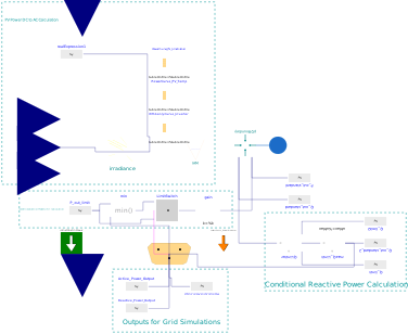
Extends from TransiEnt.Basics.Icons.SolarElectricalModel.
Information
1. Purpose of model
The purpose of this model is to calculate the power of a photovoltaic (PV) module or several modules with an controllable inverter. The active power generation can be limited, the reactive power can be adjusted based on the active power and apparent power.
2. Level of detail, physical effects considered, and physical insight
Model is based on empiric equations and PV manufacturers data. Optical losses are being consideres due to loss factors for soiling and refraction and reflexion (contained in the incidence angle modification). Degradation of the modules and inverter consumption is not included in the model.
3. Limits of validity
The model has been validated with System Advisor Model simulation results [1] for fixed PV arrays without shading influences. The results are best with Tilt angle of ~30°.
The model has not been entirely validated for sun tracking. Disabling Incidence Angle Modifications seems to improve results with tracking enabled.
4. Interfaces
Input:
DNI_in for direct normal irradiation
DHI_in for diffuse horizontal irradiation
T_in for ambient temperature
WindSpeed_in for wind speed
controlBus for P_limit, SignalActive and Q_input (conditional interface activated by parameter useControlBus)
Output:
epp for connection to a complex root mean square grid simulation
controlBus for P_out, Q_out (conditional interface activated by parameter useControlBus)
5. Nomenclature
See parameter and variable descriptions in the code.
6. Governing Equations
6.1. Plane of Array (POA) Irradiation
The POA irradiation is being calculated in IrradianceOnATiltedSurface model.
6.2. Module Temperature
The module temperature T_module is estimated following [2]:
T_module = 273.15 + T_in + POA_Irradiation * (exp(-3.47 - 0.0594 * WindSpeed_in))
6.3. Direct Current Power output P_dc
P_dc is calculated by:
P_dc = PowerCurve_PV_Irradiation.y[1] * PowerCurve_PV_Temp.y[1] / Pmpp * (100 - LossesDC) / 100 * P_inst / Pmpp
PowerCurve_PV_Irradiation.y[1] is the Maximum Power Point (MPP) power at the current Irradiation at reference temperature of the simulated module. PowerCurve_PV_Temp.y[1] is the MPP power at the current temperature at reference irradiation of the simulated module. Pmpp is the MPP power at reference conditions of the simulated module. LossesDC are the losses in % through Connections, Wiring, Tracking Error and Mismatches. P_inst is the cumulated installed power.
6.4. Active Power Output epp.P
P_out is calculated by:
if P_dc*EfficiencyCurve_Inverter.y[1]*(100-LossesAC)/100 < P_inverter then
P_out=P_dc*EfficiencyCurve_Inverter.y[1]*(100-LossesAC)/100;
else
P_out=P_inverter;
end if;
epp.P is calculated by:
if controlBus.SignalActive then
epp.P = min(controlBus.P_limit, P_out);
else
epp.P = P_out;
end if;
EfficiencyCurve_Inverter.y[1] is the efficiency of the simulated inverter depending on the inverter load. If P_dc exceeds the inverter power P_inverter the output is cut off to P_inverter as its maximum, where P_inverter is defined as the installed PV DC power divided by DCtoACratio which is the ratio between installed DC and AC power. LossesAC are losses on the AC side not included in inverter efficiency.
6.4. Reactive Power Output epp.Q
epp.Q has to be set externally over controlBus.Q_input and is limited by Q_max_calc (Variable) and Q_max (Parameter) over two conditional limiters.
Q_max_calc^2 = S_max^2 - P_out^2
if useControlBus and use_ReactivePower then
epp.Q = min(controlBus.Q_input, Q_max_calc, Q_max);
else
epp.Q = 0 VAr;
end if;
7. Remarks for Usage
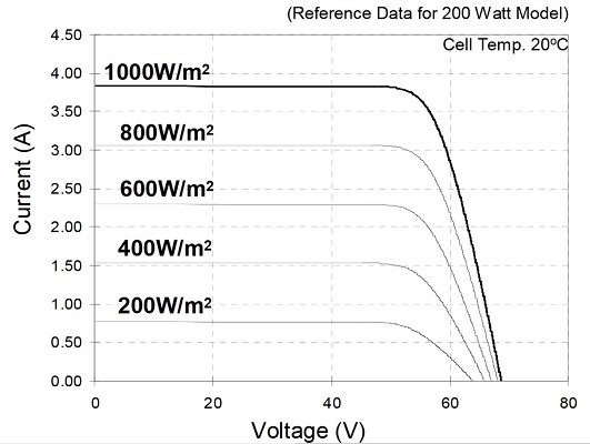
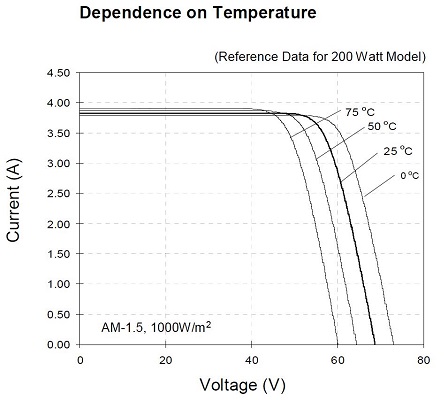
For the calculation of the output power, manufacturer datasheets are to be digitalized, e.g. with http://arohatgi.info/WebPlotDigitizer/. This is an example for a Sanyo HIT 200BA module [2]. Digitalize the following figures:
 [2]
[2]
 [2]
[2]
After digitalization, calculate the MPP power of each curve and write those to a record as shown in TransiEnt.Producer.Electrical.Photovoltaics.Advanced_PV.Characteristics. For the above shown curves the record is:
record PVModule_Characteristics_Sanyo_HIT_200_BA3
extends Generic_Characteristics_PVModule(
MPP_dependency_on_Temp_fixedIrradiation=[
0,214.3545548;
25,200.8472531;
50,187.3094253;
75,173.1095017],
MPP_dependency_on_irradiation_fixedTemperature=[
0,0;
200,37.69290789;
400,77.36493756;
600,117.7097234;
800,159.0501238;
1000,201.294124]);
annotation (Icon(coordinateSystem(preserveAspectRatio=false)), Diagram(coordinateSystem(preserveAspectRatio=false)));
end PVModule_Characteristics_Sanyo_HIT_200_BA3;
Hereby the firste table (MPP_dependency_on_Temp_fixedIrradiation) gives the MPP power (second column) for fixed irradiation and different temperatures (first column) and the second table (MPP_dependency_on_irradiation_fixedTemperature) gives the MPP power (second column) for fixed temperature and different irradiation (first column).
8. Validation
The model has been validated with System Advisor Model simulation results [1] for bigger fixed PV arrays without shading influences.
IWEC or TMY data was used in Hamburg, Munich and Miami.
9. References
[1] https://sam.nrel.gov/
[2] http://store.affordable-solar.com/site/doc/Doc_sanyo_specs_20061106173925.pdf
10. Version History
Advanced_PV by Oliver Schülting and Ricardo Peniche, Technische Universität Hamburg, Institut für Energietechnik, 2015
Revision by Tobias Becke, Technische Universität Hamburg, Institut für Energietechnik, 2016
Adjusted by Tom Steffen, Techische Universität Hamburg, Institut für Elektrische Energietechnik, 2025
Parameters
| Type | Name | Default | Description |
|---|---|---|---|
| Modelica.Units.SI.Power | P_inst | 200 | combined installed power |
| Modelica.Units.SI.Power | Pmpp | 200 | peak power of one module |
| Modelica.Units.SI.Voltage | V_nominal | 400 | Nominal Voltage |
| Modelica.Units.SI.Area | Area | 1.18 | area of one complete module |
| Real | Strings | 1 | choose amount of strings |
| Real | GroundCoverageRatio | 0.3 | ratio of covered ground of modules to area of modules |
| Real | LossesDC | 4.44 | losses in % through connections, wiring, tracking error and mismatches |
| Real | LossesAC | 1 | losses on AC side not included in inverter efficiency |
| Real | Soiling | 5 | Average annual losses of radiation in % due to soiling |
| TransiEnt.Producer.Electrical.Photovoltaics.Advanced_PV.Characteristics.Generic_Characteristics_PVModule | PVModuleCharacteristics | TransiEnt.Producer.Electrical.Photovoltaics.Advanced_PV.Characteristics.PVModule_Characteristics_Sanyo_HIT_200_BA3() | Characteristics of PV Module |
| Boolean | integratePowerDc | false | true if power shall be integrated |
| Boolean | integratePowerOut | false | true if output power shall be integrated |
| Inverter | |||
| Real | DCtoACratio | 1.1 | ratio between installed DC and AC power |
| Boolean | use_ReactivePower | false | true, if reactive power can be set |
| Modelica.Units.SI.ApparentPower | S_max | P_inst | maximum apparent power |
| Modelica.Units.SI.ReactivePower | Q_max | 0.3*S_max | maximum reactive power |
| Irradiance › Solartime | |||
| Modelica.Units.SI.Angle | longitude_local | Modelica.Units.Conversions.from_deg(10) | longitude of the local position, east positive, 10 East for Hamburg |
| Modelica.Units.SI.Angle | longitude_standard | Modelica.Units.Conversions.from_deg(15) | needed for calculation of coordinated universal time (utc), 15 for central european time, 30 for central european summer time |
| Irradiance › Extraterrestrial Irradiance | |||
| Modelica.Units.SI.Angle | latitude | Modelica.Units.Conversions.from_deg(53.55) | latitude of the local position, north positive, 53,55 North for Hamburg |
| Modelica.Units.SI.Angle | slope | Modelica.Units.Conversions.from_deg(30) | slope of the tilted surface, assumption |
| Modelica.Units.SI.Angle | surfaceAzimuthAngle | 0 | surface azimuth angle |
| Boolean | input_POA_irradiation | false | If true, plane of array irradiation is used as input instead of DNI and DHI |
| IAM › General | |||
| Integer | kind | 1 | IAM for direct Irradiance |
| Real | constant_iam_dir | 1 | constant IAM for direct irradiation |
| Real | constant_iam_diff | 1 | constant IAM for diffuse irradiation |
| Real | constant_iam_ground | 1 | constant IAM for ground-reflected irradiation |
| Real | b0 | 1 | assumption: constant b0-value for IAM=1-b0*(1/cos(theta)-1) |
| Real | iam_SRCC | {1, 1, 1, 1, 1, 1, 1, 1} | IAM for theta = 0, 10, 20, ..., 70 |
| Modelica.Units.NonSI.Angle_deg | theta | {0, 10, 20, 30, 40, 50, 60, 70} | |
| Irradiance › Skymodel | |||
| Real | reflectance_ground | 0.2 | reflectance of the ground |
| Boolean | direct_normal | true | Is the direct irradiance measured on a surface normal to irradiance? |
| External Control | |||
| ControlType | controlType | TransiEnt.Basics.Types.ControlType.Internal | Type of control (see enumeration) |
| Boolean | useControlBus | false | enable expandable controller with ability to control power output |
Connectors
| Type | Name | Default | Description |
|---|---|---|---|
| TransiEnt.Basics.Interfaces.General.TemperatureCelsiusIn | T_in | ambient temperature in Celcius | |
| TransiEnt.Basics.Interfaces.Ambient.VelocityIn | WindSpeed_in | wind speed in m/s | |
| TransiEnt.Basics.Interfaces.Electrical.ComplexPowerPort | epp | power output | |
| Modelica.Blocks.Interfaces.RealInput | POA_radiation_in | Radiation on module in W/m^2 | |
| TransiEnt.Basics.Interfaces.Ambient.IrradianceIn | DNI_in | Direct Normal Irradiation in W/m^2 | |
| TransiEnt.Basics.Interfaces.Ambient.IrradianceIn | DHI_in | Diffuse Horizontal Irradiation in W/m^2 | |
| TransiEnt.Basics.Interfaces.Ambient.IrradianceOut | POA_Irradiation | ||
| TransiEnt.Basics.Interfaces.General.ControlBus | controlBus |
Components
Contents
| Name | Description |
|---|---|
 ProducerCosts ProducerCosts | |
 Skymodel Skymodel |