
modelTestHeatPumpPartialLoad
Information
1. Purpose of model
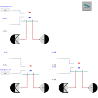
Test environment for HeatPumpPartialLoad. Three instances show the coefficient of performance (COP) for a variable temperature lift, a variable partial load and the combination of both.
2. Level of detail, physical effects considered, and physical insight
(Purely technical component without physical modeling.)
3. Limits of validity
(Purely technical component without physical modeling.)
4. Interfaces
(no elements)
5. Nomenclature
(no elements)
6. Governing Equations
(no equations)
7. Remarks for Usage
Test cases:
heatPumpPartialLoad(temperature lift test): constant heat flow set point of -50 kW, source temperature 280 K ± 15 K (sine, period 100 s); shows the influence of the temperature lift.heatPumpPartialLoad1(partial load test): heat flow set point -45 kW ± 15 kW (sine, period 100 s), constant source temperature of 280 K; shows the influence of the partial load.heatPumpPartialLoad2(combined test): both sine sources as above and in phase, i.e. the lowest heat demand (30 kW) coincides with the highest source temperature (295 K); shows the combined influence.
All instances use parameter set 1 (selectHP = 1, 60 kW brine to water) with heatSourceType = "Liquid". On the heat sink side, water (TILMedia_Water) enters portA at 4 bar and 310 K; the mass flow rate of 0.5 kg/s is imposed by the boundary at portB. The simulation covers one sine period (0 s to 100 s, Dassl).
Recommended variables for plotting: COP, electricConsumption, T_hot, T_cold and sinkTemperature of the three instances.
Expected trends: The COP increases with the source temperature (temperature lift test). It decreases with increasing heat flow rate (partial load test), because the tested range of 30 kW to 60 kW lies above the heat flow rate of maximum COP/COPCarnot (1/b2 = 26.7 kW for parameter set 1). In the combined test both effects add up.
8. Validation
(no validation or testing necessary)
9. References
(no remarks)
10. Version History
Model created by Michael Vieth (michael.vieth@tuhh.de) on 02.10.2026
Components
| Type | Name | Default | Description |
|---|---|---|---|
| HeatPumpPartialLoad | heatPumpPartialLoad1 | Partial load test: variable heat flow set point, constant source temperature | |
| TransiEnt.SimCenter | simCenter | Global settings; fluid1 = TILMedia water as heat sink medium | |
| TransiEnt.Components.Boundaries.FluidFlow.BoundaryVLE_pTxi | boundaryVLE_pTxi | Partial load test: heat sink inlet, water at 4 bar and 310 K | |
| TransiEnt.Components.Boundaries.FluidFlow.BoundaryVLE_Txim_flow | boundaryVLE_Txim_flow | Partial load test: heat sink outlet, imposed mass flow rate of 0.5 kg/s | |
| Modelica.Blocks.Sources.RealExpression | realExpression | Partial load test: constant source temperature of 280 K | |
| Modelica.Blocks.Sources.Sine | sine | Partial load test: heat flow set point -45 kW +/- 15 kW, period 100 s | |
| HeatPumpPartialLoad | heatPumpPartialLoad | Temperature lift test: constant heat flow set point, variable source temperature | |
| TransiEnt.Components.Boundaries.FluidFlow.BoundaryVLE_pTxi | boundaryVLE_pTxi1 | Temperature lift test: heat sink inlet, water at 4 bar and 310 K | |
| TransiEnt.Components.Boundaries.FluidFlow.BoundaryVLE_Txim_flow | boundaryVLE_Txim_flow1 | Temperature lift test: heat sink outlet, imposed mass flow rate of 0.5 kg/s | |
| Modelica.Blocks.Sources.RealExpression | realExpression1 | Temperature lift test: constant heat flow set point of -50 kW | |
| Modelica.Blocks.Sources.Sine | sine1 | Temperature lift test: source temperature 280 K +/- 15 K, period 100 s | |
| HeatPumpPartialLoad | heatPumpPartialLoad2 | Combined test: variable heat flow set point and source temperature | |
| TransiEnt.Components.Boundaries.FluidFlow.BoundaryVLE_pTxi | boundaryVLE_pTxi2 | Combined test: heat sink inlet, water at 4 bar and 310 K | |
| TransiEnt.Components.Boundaries.FluidFlow.BoundaryVLE_Txim_flow | boundaryVLE_Txim_flow2 | Combined test: heat sink outlet, imposed mass flow rate of 0.5 kg/s | |
| Modelica.Blocks.Sources.Sine | sine2 | Combined test: heat flow set point -45 kW +/- 15 kW, period 100 s | |
| Modelica.Blocks.Sources.Sine | sine3 | Combined test: source temperature 280 K +/- 15 K, period 100 s (in phase with sine2) |