
modelControlVolumeL4
Extends from TransiEnt.Basics.Icons.Fluid_Volume.
Information
1. Purpose of model
Discretized aquifer control volume model for 2D (radial-vertical) flow. Implements the coupled energy balance, mass continuity, and Darcy pressure equations for an [N_r × N_z] grid of aquifer cells. Includes optional buoyancy-driven vertical flow and temperature-dependent fluid properties (density, dynamic viscosity).
2. Level of detail, physical effects considered, and physical insight
L4: Fully discretized control volume array. Each cell is ideally mixed (lumped). Physical effects considered:
- Radial and vertical mass transport (Darcy flow, buoyancy)
- Enthalpy transport by mass flow
- Heat conduction via thermal resistors (coupled through port[N_r, N_z])
- Temperature-dependent dynamic viscosity and density
3. Limits of validity
- No chemical reactions; single-component fluid.
- Density differences at radial cell interfaces are interpolated linearly between adjacent cells.
- Buoyancy switched on/off via Setting record boolean.
4. Interfaces
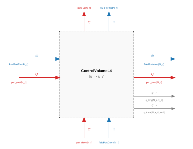
fluidPortEast[N_z]: fluid inlet at inner radial boundary (Fluid, inlet)
fluidPortWest[N_z]: fluid outlet at outer radial boundary (Fluid, outlet)
fluidPortUp[N_r]: fluid outlet at top boundary (Fluid, outlet)
fluidPortDown[N_r]: fluid inlet at bottom boundary (Fluid, inlet)
port[N_r, N_z]: internal heat port array, one per cell — connected externally to the thermal resistor network (Heat)
q_long[N_r, N_z]: radial Darcy velocity output for dispersion calculation (Signal, outlet)
q_trans[N_r, N_z+1]: vertical Darcy velocity output for dispersion calculation (Signal, outlet)
5. Nomenclature
|
T[N_r, N_z] |
cell temperature [K] |
|
p[N_r, N_z] |
cell pressure [Pa] |
|
U[N_r, N_z] |
internal energy of cell [J] |
|
H_flow[N_r+1, N_z] |
enthalpy flow at radial interfaces [W] |
|
m_flow[N_r+1, N_z] |
radial mass flow rate at interfaces [kg/s] |
|
port[i,j].Q_flow |
heat flow from thermal resistors [W] |
|
q_long[N_r, N_z] |
radial Darcy velocity at cell centre (for dispersion) [m/s] |
|
q_trans[N_r, N_z+1] |
vertical Darcy velocity at horizontal cell interface (for dispersion) [m/s] |
|
n |
porosity of aquifer [-] |
|
rho_s |
density of aquifer solid [kg/m³] |
|
Cp_s |
specific heat capacity of aquifer solid [J/(kg·K)] |
|
geo.V[i,j] |
cell volume [m³] |
|
rho_l |
fluid density taken from TILMedia [kg/m³] |
|
Cp_l |
specific heat capacity of fluid taken from TILMedia [J/(kg·K)] |
|
H_flow_buoyancy[N_r, N_z+1] |
buoyancy-driven enthalpy flow rate [W] |
|
m_flow_buoyancy[N_r, N_z+1] |
buoyancy-driven mass flow rate [kg/s] |
|
delta_p_darcy[N_r+1, N_z] |
Darcy pressure loss at each radial cell interface [Pa] |


6. Governing Equations
Energy balance for each aquifer cell (i,j):

Mass continuity for each aquifer cell:

Static pressure balance (Darcy pressure loss calculated in DarcyFlow_horizontal):

7. Remarks for Usage
Requires an enclosing model to declare inner Modelica.SimCenter (for fluid type) and inner variables delta_p_darcy, rho_FM, f_eta, delta_p_v, rho_FM_v, f_eta_v (accessed via inner/outer from DarcyFlow sub-models). Thermal resistors are connected externally via port[N_r, N_z].
8. Validation
Validated in Validation.Buoyancy.Val_homogenLayer.mo
9. References
(no remarks)
10. Version History
Model created by Markus Gillner (markus.gillner@tuhh.de), May 2026
Model revised by Markus Gillner (markus.gillner@tuhh.de), June 2026
- Corrected the interface list (removed non-existent port_east/west/up/down; the model has a single internal heat port array port[N_r, N_z]), fixed a character-encoding artifact, and corrected the delta_p_darcy dimension.
Parameters
| Type | Name | Default | Description |
|---|---|---|---|
| SI.Temperature | T_start | Parameters.T_initial | Start value for temperature |
Connectors
| Type | Name | Default | Description |
|---|---|---|---|
| TransiEnt.Basics.Interfaces.Thermal.FluidPortIn[N_z] | fluidPortEast | ||
| TransiEnt.Basics.Interfaces.Thermal.FluidPortOut[N_z] | fluidPortWest | ||
| TransiEnt.Basics.Interfaces.Thermal.FluidPortIn[N_r] | fluidPortDown | ||
| TransiEnt.Basics.Interfaces.Thermal.FluidPortOut[N_r] | fluidPortUp | ||
| Modelica.Thermal.HeatTransfer.Interfaces.HeatPort_a[N_r,N_z] | port | ||
| Modelica.Blocks.Interfaces.RealOutput[N_r,N_z + 1] | q_trans | ||
| Modelica.Blocks.Interfaces.RealOutput[N_r,N_z] | q_long |
Components
| Type | Name | Default | Description |
|---|---|---|---|
| SI.Mass[N_r,N_z] | m | ||
| SI.SpecificEnthalpy[N_r,N_z] | h | ||
| SI.Temperature[N_r,N_z] | T | ||
| SI.Pressure[N_r,N_z] | p | ||
| Real[N_r,N_z] | drhodt | ||
| Real[N_r,N_z] | der_T | ||
| SI.Energy[N_r,N_z] | U | ||
| SI.SpecificHeatCapacity[N_r,N_z] | c_w | ||
| SI.EnthalpyFlowRate[N_r + 1,N_z] | H_flow | ||
| SI.MassFlowRate[N_r + 1,N_z] | m_flow | ||
| SI.MassFlowRate[N_r,N_z + 1] | m_flow_buoyancy | mass flow induced by temperature driven density differences | |
| SI.EnthalpyFlowRate[N_r,N_z + 1] | H_flow_buoyancy | ||
| SI.Density[N_r + 1,N_z] | rho_FM | ||
| SI.Density[N_r,N_z + 1] | rho_FM_v | Mean Density at cross surface area of control volumes | |
| SI.DynamicViscosity[N_r + 2,N_z] | f_eta | temperature and density dependent dynamic viscosity | |
| SI.PressureDifference[N_r + 1,N_z] | delta_p_darcy | ||
| SI.PressureDifference[N_r,N_z + 1] | delta_p_v | pressure difference between two control volumes in vertical neighbourhood | |
| SI.DynamicViscosity[N_r,N_z + 2] | f_eta_v | ||
| TILMedia.VLEFluid_ph[N_z] | fluidEast | ||
| TILMedia.VLEFluid_ph[N_z] | fluidWest | ||
| TILMedia.VLEFluid_pT[N_r,N_z] | bulk | ||
| TILMedia.VLEFluid_ph[N_r] | fluidUp | ||
| TILMedia.VLEFluid_ph[N_r] | fluidDown | ||
| ClaRa.SimCenter | simCenter | ||
| PressureLoss.DarcyFlow_horizontal | darcyFlow_horizontal | ||
| Records.Subsurface_Basic | Parameters | ||
| Geometry | geo | ||
| PressureLoss.DarcyFlow_vertical | darcyFlow_vertical | ||
| Records.Setting | setting |