Accessories Tutorial
Tutorial - Defining a new accessories model
The following process will demonstrate how to create a new
accessories model using these interface definitions. This tutorial
will guide you through building an accessory subsystem with
a power steering pump and alternator. Both will be modelled
using speed dependant torque loss maps.
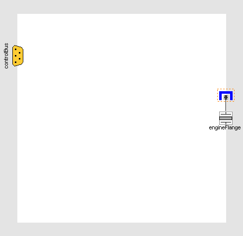
- Create a new model that extends
VehicleInterfaces.Accessories.Interfaces.Base, it
should look like this:
- In the component browser, right click on Base
and select Parameters from the context menu to
produce the following parameter dialog:
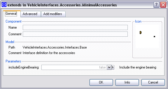
- This dialog allows you to enable/disable the optional bearing
connectors within the engineFlange by setting
includeEngineBearing as required.
- You can now define your accessory model as required
Adding an alternator and power steering pump
The following steps demonstrate how to create a simple
accessories model. The subsystem will include an alternator and
power steering pump that are modelled separately but both use
speed-dependant torque loss maps.
Starting from step 2 above.
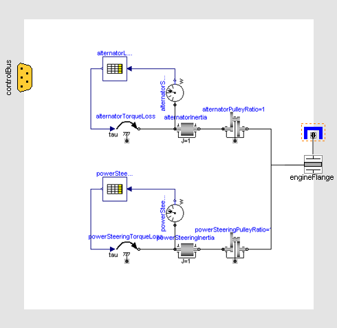
- Add the following blocks and connections to the diagram:
- Next, we need to check to see if any connections to the control
signal bus are required for the driveline, see a complete
list of the minimum connections required. In this case we don't
need to add any signals to the control signal bus.
- The model is now complete and should check successfully and can
be used in any model compatible with the VehicleInterfaces
library
Generated at 2026-06-23T20:19:05Z by OpenModelicaOpenModelica 1.26.9 using
GenerateDoc.mos