Brakes Tutorial
Tutorial - Defining a new brakes model
The following process will demonstrate how to create a new
brakes model using these interface definitions. This tutorial will
guide you through building a braking system for
a passenger car, i.e. a vehicle with 4 wheels.
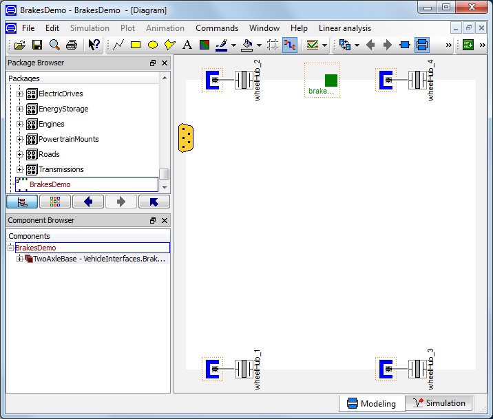
- Create a new model that extends
VehicleInterfaces.Brakes.Interfaces.TwoAxleBase,
it should look like this:
- In the component browser, right click on
TwoAxleBase and select Parameters
from the context menu to produce the following parameter
dialog
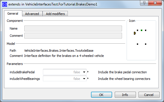
- This dialog allows you to enable/disable the optional
connections by setting includeWheelBearings and
includeBrakePedal as required for your new brakes
model. The wheelHub connectors are of the type
Modelica.Mechanics.MultiBody.Interfaces.FlangeWithBearing, the
parameter includeWheelBearings controls whether
the bearing connectors within the wheelHubs is enabled or not.
- You can now define your brakes model as required.
Creating a simple braking system example
The following steps demonstrate how to create anbsp;simple
braking system model. The brakes will be modelled using the
standard brakes component from the Modelica standard library.
A position sensor will measure the brake pedal position and
a 1D table block will be used to convert this to a force
that will be applied to each wheel brake. The reactions in to the
wheel carriers will not be modelled.
Starting from step 3 above.
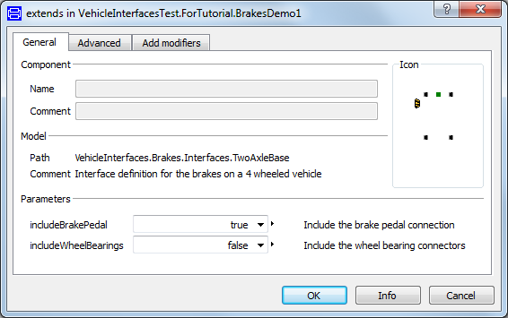
- First, decide which of the optional connectors are required in
the model. For this example we need the brake pedal connection but
not the wheel bearing connector
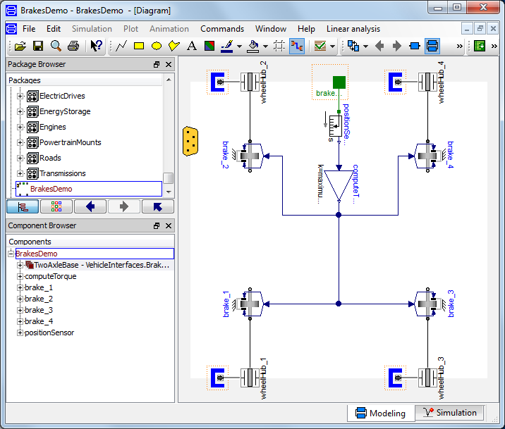
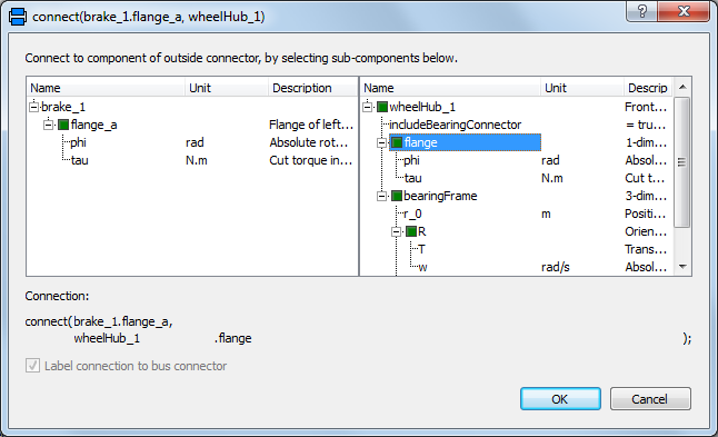
- Add the following blocks and connections to the diagram. When
you draw the connections from the brake components to the wheelHub
connectors the dialog box shown below will appear asking which
connector within the wheelHub connector you would like to make the
connection to. As we are modelling the brakes as a 1D system
you should select flange from the list of options
which is the 1D connector within the wheelHub connector.
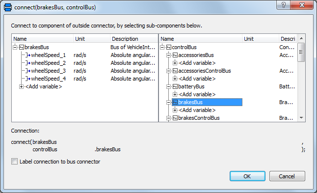
- Next, we need to check to see if any connections to the control
signal bus are required for the brakes, see a complete list
of the minimum connections required. In this case we need to
add the four individual wheel speeds to the control signal bus and
this can be done by connecting speed sensors to each wheel and then
connecting these to the signal bus. As the wheel speed signals are
added to the brakesBus we first need to add this connector. The
brakesBus connector is
VehicleInterfaces.Interfaces.BrakesBus. This
should be connected to the controlBus; when this
connection is made the following dialog is produced and should be
completed as shown.
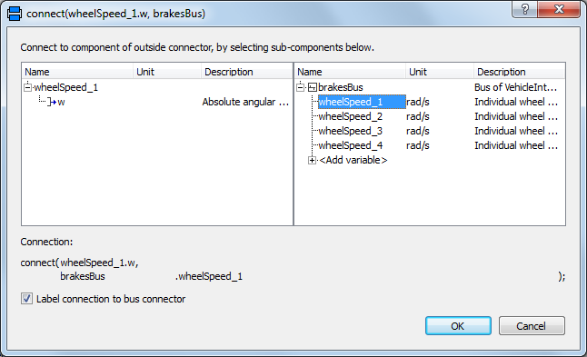
- When the connections between the sensors and the brakesBus
connector are added the dialog below appears and should be
completed with the correct index for all four wheel speeds being
measured.
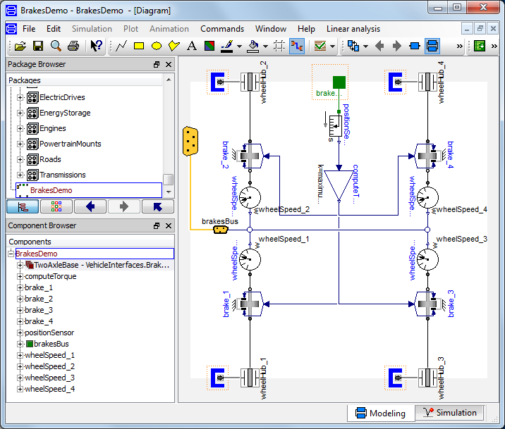
- The model is now complete and should check successfully and can
be used in any model compatible with the VehicleInterfaces library
assuming the selected Driver model also uses the brake pedal
connection.
Generated at 2026-07-26T20:40:21Z by OpenModelicaOpenModelica 1.27.0 using
GenerateDoc.mos