Transmissions Tutorial
Tutorial - Defining a new manual transmission model
The following process will demonstrate how to create a new
manual transmission model using this interface definition.
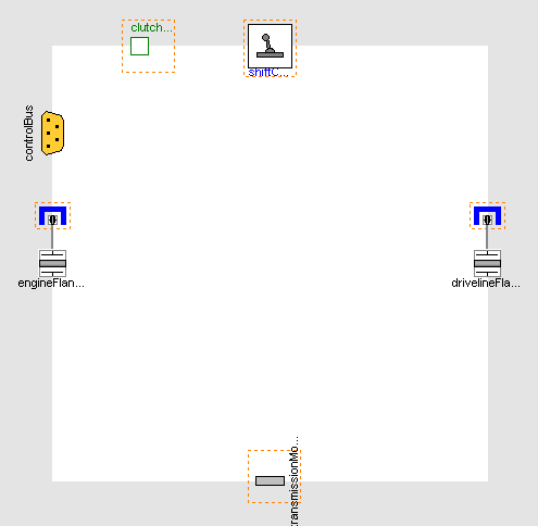
- Create a new model that extends
VehicleInterfaces.Transmissions.Interfaces.BaseManualTransmission,
it should look like this:
- In the component browser, right click on Base
and select Parameters from the context menu to
produce the following parameter dialog
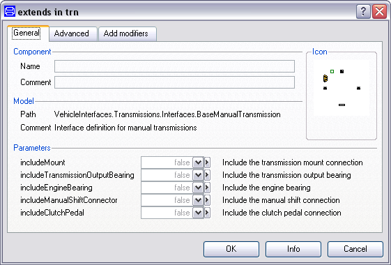
- This dialog allows you to enable/disable the optional
connections by setting includeClutchPedal,
includeManualShiftConnector and
includeMount as required for your new transmission
model. The engineFlange and
drivelineFlange connectors are of the type
Modelica.Mechanics.MultiBody.Interfaces.FlangeWithBearing, the
parameters includeEngineBearing and
includeDrivelineBearing controls whether the
bearing connectors within these connections are enabled or
not.
- You can now define your transmission model as required
Creating the MinimalTransmission example
The following steps demonstrate how to create a basic
transmission model. The transmission model will consist of
a fixed single ratio between the input and output shafts. No
torque reaction in to the transmission housing will be
modelled.
Starting from step 3 above.
- First, decide which of the optional connectors are required to
model. For this example we don't need any of the optional
connections
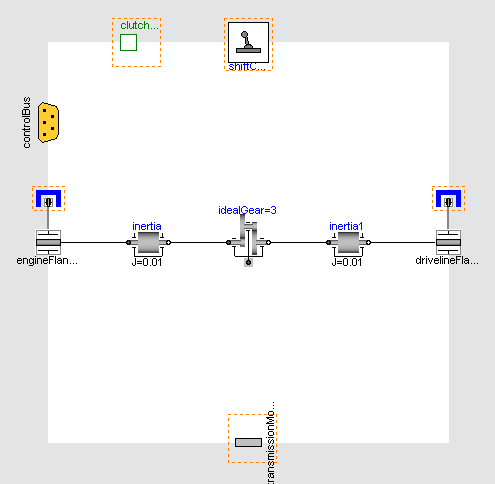
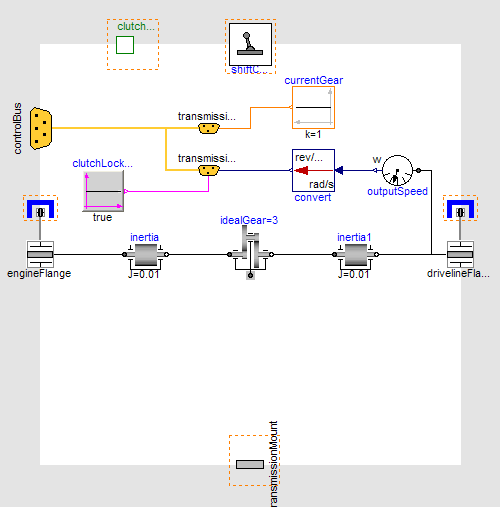
- Add the following blocks and connections to the diagram
- Next, we need to add the required connections to the control
signal bus for the transmission, see here for
a complete list of the minimum connections required. As we are
creating a manual transmission model we need to add three
signals to the transmissionBus which is part of the controlBus. We
need to put the transmission output speed, current gear and the
clutch state on to the transmissionBus. As this is a simple
single gear transmission the current gear and clutch state can be
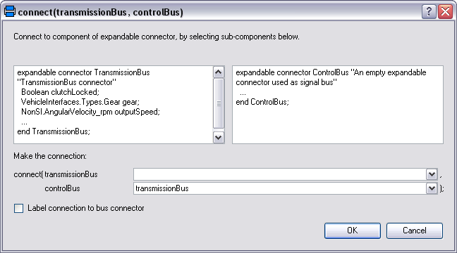
set as constants. Start by adding the transmissionBus connector
which can be found at
VehicleInterfaces.Interfaces.TransmissionBus and
connect this to the controlBus. When this connection is made the
following dialog will be produced and should be completed as
shown.
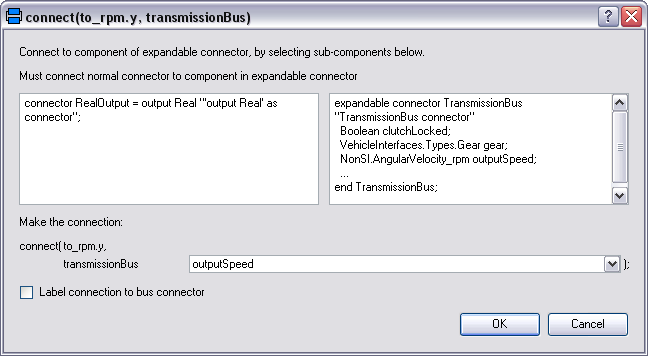
- We can now connect the constants for clutch state and current
gear to the transmissionBus. The transmission output speed needs to
be in the correct units, in this case rev/min (or rpm). Add
a rotational speed sensor and a unit conversion block
from Modelica.Blocks.Math.UnitConversions, set the
conversion block to convert to rpm. When you create the connection
between the transmissionBus and one of these blocks a dialog
like the one below will be produced. You will need to complete the
dialog using one of the following names:
- gear
- clutchLocked
- outputSpeed
- The model is now complete and should check successfully and can
be used in any model compatible with the VehicleInterfaces
library
Generated at 2026-07-26T20:40:21Z by OpenModelicaOpenModelica 1.27.0 using
GenerateDoc.mos