Example used in DHC 2021 conference
This network can be characterized as a three-level district heating
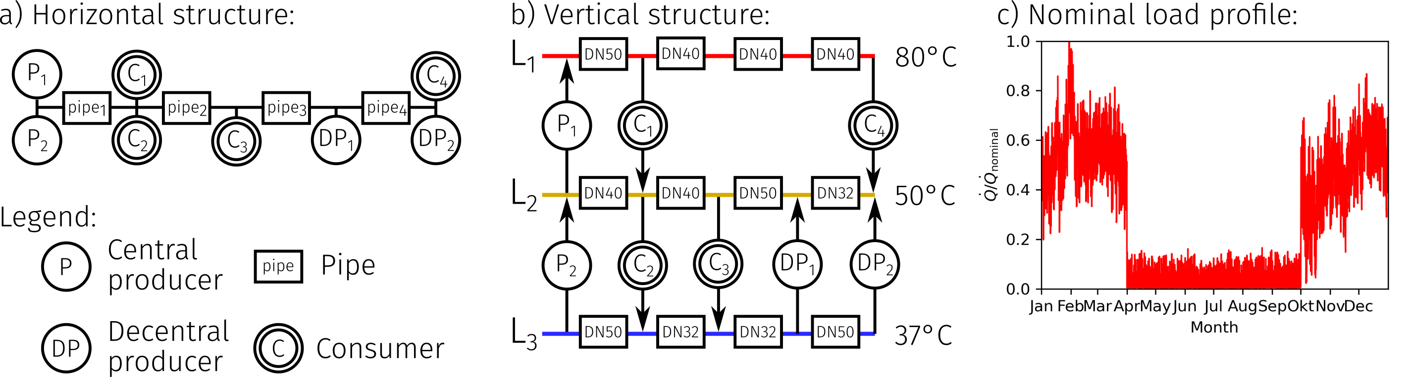
network with decentralized feed-in. A graphical scheme of this
network is shown in the figure (a) and (b) below. The horizontal
structure of the district heating (DH) network from Figure (a)
represents the geographical alignment of the network. It shows a
simple branch structure without loops, to which four consumers
(C1-C4), two central producers (P1, P2) and two decentral producers
(DP1 and DP2) are connected. The vertical network structure of the
used example from Figure (b) represents a vertical plane
perspective of the network in which the multiple network levels and
their interaction with consumers and producers can be identified.
Within the vertical network structure three network levels called
L1, L2 and L3 are available. It is assumed that the network set
temperatures decrease from L1 to L3. This network concept can be
advantageous in areas with existing and new buildings and several
available heat sources. Consumers C1 and C4 can be characterized as
high temperature consumers which are located between L1 and L2.
These types of consumers are assumed to meet their space heating
demand through radiators with system design temperatures of 70/50
°C and their domestic hot water (DHW) demand through storage tank
charging systems. This limits the lowest possible supply
temperature on the building side to 60 °C due to thermal
disinfection requirements for DHW. Therefore, the set temperature
of L1 varies within a temperature range between 80-65 °C with
regards to the ambient temperature. Consumer C2 and C3 can be
characterized as low temperature consumer types which are located
between L2 and L3. These types of consumers are assumed to meet
their space heating demands by floor heating systems with design
temperatures of 45/35 °C. It is assumed that these consumer types
cover their space heating demands through floor heating systems
with design temperatures of 45/35 °C and their hot water demand
through freshwater stations. Thus, supply temperatures can be
significantly lower than 60 °C. Based on this characterization, the
set temperature of L2 is defined to be constant at 50 °C throughout
the year. The resulting nominal temperature of L3 is 37 °C. It is
assumed that all consumers are designed passively, i.e., the load
control is realized by valves. This requires a sufficient pressure
difference between supply and return at each consumer substation.
Heat production in the network is realized by two central producer
units P1 and P2 which are located between L1 and L2 as well as L2
and L3. Furthermore, two decentralized producer units DP1 and DP2
are located between L2 and L3 and provide a constant heat flow to
the network. Centralized and decentralized producer types are
actively designed, i.e., their individual pumps ensure a sufficient
pressure difference to feed the network.
Generated at 2026-07-26T20:40:21Z by OpenModelicaOpenModelica 1.27.0 using
GenerateDoc.mos