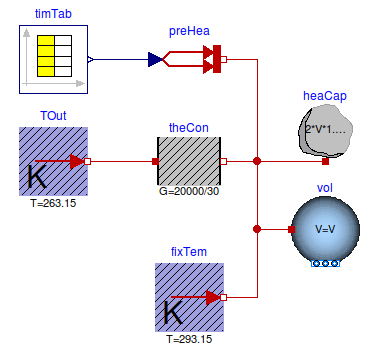
This part of the system model implements the room with a heat gain. The room is simplified as a volume of air, a prescribed heat source for the internal convective heat gain, and a heat conductor for steady-state heat conduction to the outside. To increase the heat capacity of the room, such as due to heat stored in furniture and in building constructions, the heat capacity of the room air was increased by a factor of three. The convective heat transfer coefficient is lumped into the heat conductor model.
This section describes step by step how we implemented the model.
First, to define the medium properties, we added the declaration
  replaceable package MediumA =
      Buildings.Media.Air;
This will allow the propagation of the medium model to all models that contain air. In this example, there is only one model with air.
We called the medium MediumA to distinguish it from
MediumW that we will use in later versions of the
model for components that have water as a medium.
We also defined the system-level parameters
  parameter Modelica.Units.SI.Volume V=6*10*3 "Room volume";
  parameter Modelica.Units.SI.MassFlowRate mA_flow_nominal = V*1.2*6/3600
    "Nominal mass flow rate";
  parameter Modelica.Units.SI.HeatFlowRate QRooInt_flow = 4000
    "Internal heat gains of the room";
to declare that the room volume is 180 m3, that the room has a nominal mass flow rate of 6 air changes per hour and that the internal heat gains of the room are 4000 Watts. These parameters have been declared at the top-level of the model as they will be used in several other models. Declaring them at the top-level allows to propagate them to other models, and to easily change them at one location should this be required when revising the model.
To model the room air, approximated as a completely mixed volume
of air, an instance of Buildings.Fluid.MixingVolumes.MixingVolume
has been used, as this model can be used with dry air or moist air.
The medium model has been set to MediumA, and the
nominal mass flow rate is set to mA_flow_nominal. The
nominal mass flow rate is used for numerical reasons and should be
set to the approximate order of magnitude. It only has an effect if
the mass flow rate is near zero and what "near zero" means depends
on the magnitude of m_flow_nominal, as it is used for
the default value of the parameter m_flow_small on the
Assumptions tag of the model. See also Buildings.Fluid.UsersGuide
for an explanation of the purpose of m_flow_small.
Since we need to increase the heat capacity of the room air to
approximate energy storage in furniture and building constructions,
we connected the instance heaCap of
Modelica.Thermal.HeatTransfer.Components.HeatCapacitor to the
heat port of the room air. The model heaCap models
energy storage. We set its capacity to C=2*V*1.2*1006 J/K.
This will increase the total heat capacity of the room air by a
factor of three.
We used the instance theCon of
Modelica.Thermal.HeatTransfer.Components.ThermalConductor to
model the thermal conductance to the ambient. Since our room should
have a heat loss of 20 kW at a temperature difference of
30 Kelvin, we set the conductance to G=20000 ⁄ 30
W/K.
We used the instance preHea of
Modelica.Thermal.HeatTransfer.Sources.PrescribedHeatFlow to
model a prescribed heat gain, such as due to internal heat source.
This model outputs the heat gain which is equal to the value of its
input signal, which is obtained from a time table.
To define a time-dependent heat gain, we instantiated the block
Buildings.Controls.OBC.CDL.Reals.Sources.TimeTable
and set its name to timTab. We set the table
parameters to
  Buildings.Controls.OBC.CDL.Reals.Sources.TimeTable timTab(
      extrapolation=Buildings.Controls.OBC.CDL.Types.Extrapolation.Periodic,
      smoothness=Buildings.Controls.OBC.CDL.Types.Smoothness.ConstantSegments,
      table=[-6, 0;
              8, QRooInt_flow;
             18, 0],
      timeScale=3600) "Time table for internal heat gain";
Note that we set the output to be a periodic signal by
configuring
extrapolation=Buildings.Controls.OBC.CDL.Types.Extrapolation.Periodic.
The first time stamp is -6 hours in order to create a table
that has a periodicity of one day. We also set the interpolation of
the data to using piece-wise constant segments. See the
documentation of Buildings.Controls.OBC.CDL.Reals.Sources.TimeTable
for the various options of this time table.
Next, we connected its output to the input of the instance
preHea.
This completes the initial version of the model. When simulating the model for 2 days, or 172800 seconds, the response shown below should be seen.
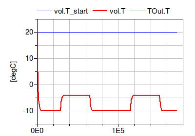
To verify the correctness of the model, we can compare the simulated results to the following analytical solutions:
When the internal heat gain is zero, the room temperature should be equal to the outside temperature.
At steady-state when the internal heat gain is 4000 Watts, the temperature difference to the outside should be Δ T = Q̇ ⁄ UA = 4000/(20000/30) = 6 Kelvin, which corresponds to a room temperature of -4°C.
Both analytical values agree with the simulation results shown in the above figure.
An alternative validation can be done by fixing the temperature of the volume to 20°C and plotting the heat flow rate that is needed to maintain this temperature. This can be implemented by connecting an instance of Modelica.Thermal.HeatTransfer.Sources.FixedTemperature as shown below.
When plotting the heat flow rate
fixTemp.port.Q_flow, one can see that the required
heat flow rate to keep the temperature at 20°C is 20
kW during night, and 16 kW during day when the heat gain is
active.
For a more realistic model of a room, the model Buildings.ThermalZones.Detailed.MixedAir could have been used. For transient heat conduction, models from the package Buildings.HeatTransfer.Conduction could have been used.
| Name | Description |
|---|---|
Modelica.Fluid.System to address issue
#311.