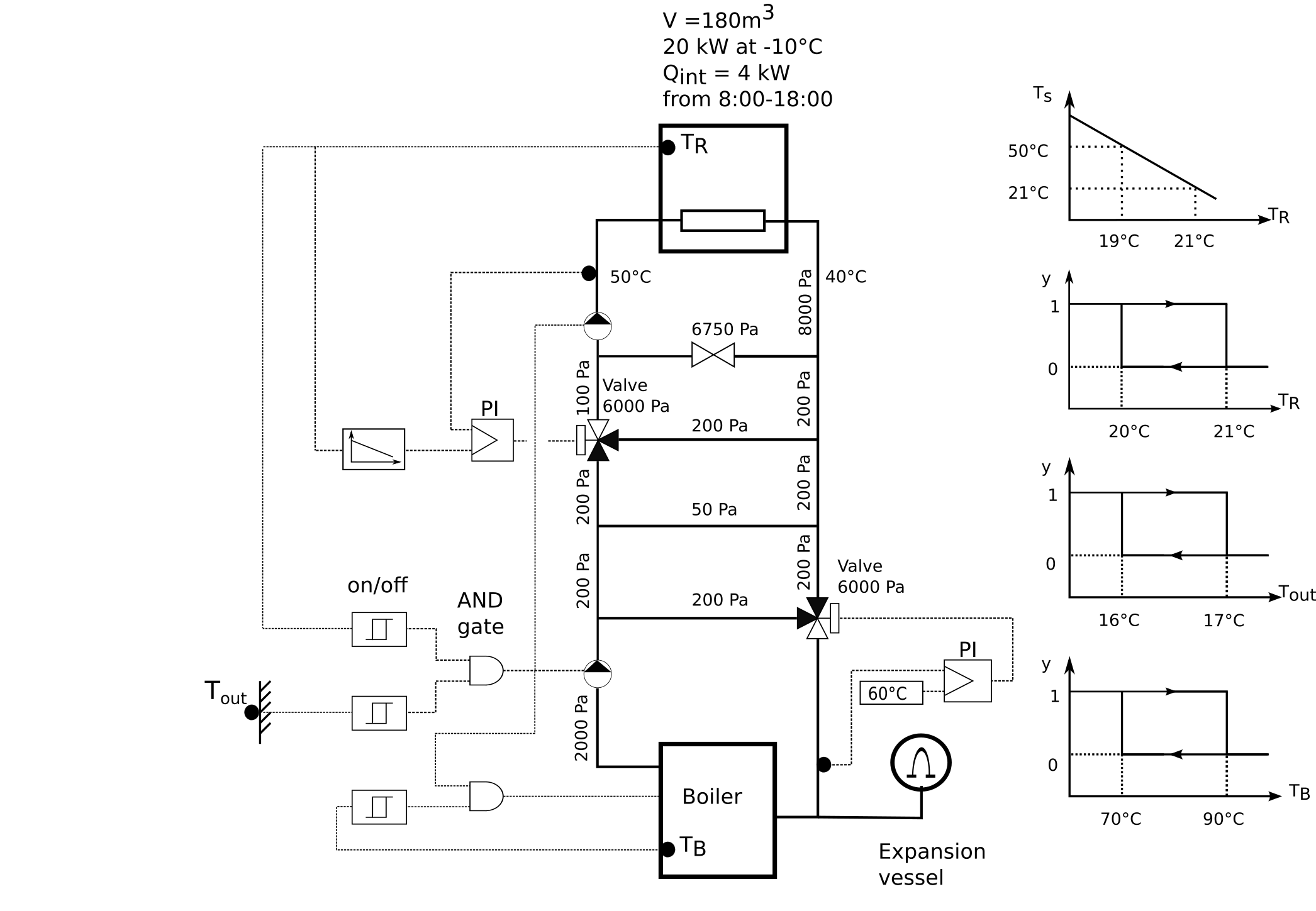
This package contains examples with step-by-step instructions for how to build a system model for a boiler with a heat load as shown in the figure below. The pressure drops of the individual flow branches and the temperatures correspond to design conditions. The heating system shall be designed to provide 20 kW, which is the load needed at -10°C outdoor temperature. This load already takes into account the heat required for air infiltration and ventilation. Using this load and the temperatures shown in the schematic drawing, the nominal mass flow rates of the individual flow branches should be computed. From 8:00 to 18:00, there is an internal heat gain of 4kW, which should not be accounted for when sizing the system.
The room volume is 180m3. To approximate the thermal storage effect of furniture and building constructions, the heat capacity of the room should be increased by a factor of three. (Modeling a detailed room heat transfer as implemented in Buildings.ThermalZones.Detailed is out of scope for this tutorial.)
The space heating shall be switched on if the outdoor temperature is below 16°C and the room temperature is below 20°C. It shall be switched off if either the outdoor temperature is above 17°C or the room temperature is above 21°C.
The model consists of
To explain the implementation of this model, the model has been created in the following stages:
| Name | Description |
|---|---|
| 1st part of the system model, consisting of the room with heat transfer | |
| 2nd part of the system model, consisting of the room with heat transfer and a radiator | |
| 3rd part of the system model, which adds the boiler loop with open loop control | |
| 4th part of the system model, which adds closed-loop control for the pumps and the boiler | |
| 5th part of the system model, which adds closed-loop control for the valves | |
| 6th part of the system model, which adds weather data and changes to PI control | |
| 7th part of the system model, which implements the on/off control using a state machine |