This part of the system model adds to the model that is implemented in Buildings.Examples.Tutorial.Boiler.System5 weather data, and it changes the control to PI control.
This model was built as follows:
First, we copied the model Buildings.Examples.Tutorial.Boiler.System5
and called it
Buildings.Examples.Tutorial.Boiler.System6.
Next, we added the weather data as shown in the figure below.
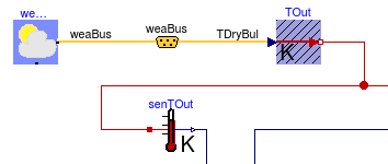
The weather data reader is implemented using
  BoundaryConditions.WeatherData.ReaderTMY3 weaDat(
    filNam="modelica://Buildings/Resources/weatherdata/USA_IL_Chicago-OHare.Intl.AP.725300_TMY3.mos")
    "Weather data reader";
The yellow icon in the middle of the figure is an instance of Buildings.BoundaryConditions.WeatherData.Bus. This is required to extract the dry bulb temperature from the weather data bus.
Note that we changed the instance TOut from
Modelica.Thermal.HeatTransfer.Sources.FixedTemperature to
Modelica.Thermal.HeatTransfer.Sources.PrescribedTemperature in
order to use the dry-bulb temperature as an input signal.
This completes the closed loop control. When simulating the model for 2 days, or 172800 seconds, the response shown below should be seen.
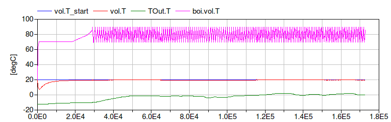
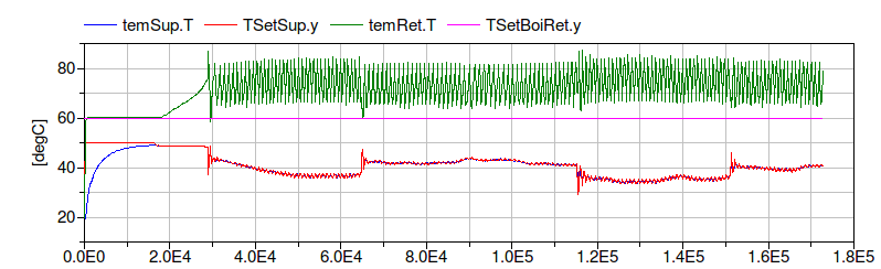
The figure shows that the boiler temperature is regulated between 70°C and 90°C, that the boiler inlet temperature is above 60°C, and that the room temperature and the supply water temperature are maintained at their set point.
| Name | Description |
|---|---|
| Medium model |
nominalValuesDefineDefaultPressureCurve=true
in the mover component to suppress a warning. This is for #3819.conPIDBoi and set
reverseActing=false to address issue #436.Modelica.Fluid.System to address issue
#311.