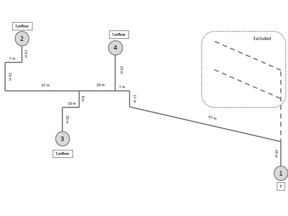
The example contains experimental data from a real district heating network. This data is used to validate this library's Buildings.Fluid.FixedResistances.PlugFlowPipe in Buildings.Fluid.FixedResistances.Validation.PlugFlowPipes.PlugFlowAIT. This model compares its performance with the original Modelica Standard Library pipes, using one discretization element per unit length of pipe. For a coarser discretization, please refer to MSLAIT2Nodes.
Note that these three models are identical, except for the pipe model that is used:
nNodes.nNodes=2.This comparison between different discretization levels and pipe models is made to check the influence of the discretization and pipe model on computation time and simulation accuracy.
The pipes' temperatures are not initialized, thus results of outflow temperature before approximately the first 10000 seconds should not be considered.
To calculate the length specific thermal resistance
R of the pipe, the thermal resistance of the
surrounding ground is added.
R=1/(0.208)+1/(2 lambda_g Modelica.Constants.pi) log(1/0.18)
Where the thermal conductivity of the ground
lambda_g = 2.4 W/(m K).
| Name | Description |
|---|---|
|
|
pipVol.