
modelCoolingTowerGroup
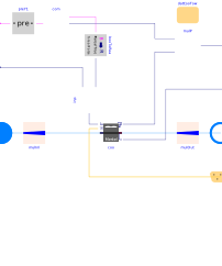
Extends from Buildings.Fluid.Interfaces.PartialTwoPortInterface (Partial model with two ports and declaration of quantities that are used by many models).
Information
This model represents a set of identical cooling towers that are piped in parallel. No actuated isolation valves are included.
Control points
The following input and output points are available.
-
Start command (VFD Run)
y1: DO signal dedicated to each unit, with a dimensionality of one -
Speed command
y: AO signal common to all units, with a dimensionality of zero -
CW supply temperature
TConWatSup: AI signal common to all units, with a dimensionality of zero
Details
Modeling approach
In a parallel arrangement, all operating units have the same operating point. This allows modeling the heat transfer from outdoor air to condenser water with a single instance of Buildings.Fluid.HeatExchangers.CoolingTowers.Merkel. Hydronics are resolved with mass flow rate multiplier components. Note that the elevation head of open-circuit cooling towers is not modeled, which is an inherent limitation of the cooling tower component model.
The fan cycling On and Off is implicitly modeled in the cooling tower component which uses a low limit of the control signal to switch to a free convection regime at zero fan power.
Parameters
| Type | Name | Default | Description |
|---|---|---|---|
| Integer | nUni | Number of units operating at design conditions | |
| Real | yFan_min | 0.1 | CT fan minimum speed |
| Modelica.Units.SI.HeatFlowRate | Q_flow_nominal | mConWatUni_flow_nominal*4200*(TConWatSup_nominal - TConWatRet_nominal) | Cooling tower design load |
| Fluid.HeatExchangers.CoolingTowers.Data.Merkel.Generic | datCooTow | Cooling tower performance data | |
| Assumptions | |||
| Boolean | allowFlowReversal (from PartialTwoPort) | true | = false to simplify equations, assuming, but not enforcing, no flow reversal |
| Nominal condition | |||
| Modelica.Units.SI.MassFlowRate | m_flow_nominal (from PartialTwoPortInterface) | Nominal mass flow rate | |
| Modelica.Units.SI.MassFlowRate | mConWatUni_flow_nominal | CW design mass flow rate (each unit) | |
| Modelica.Units.SI.MassFlowRate | mConWat_flow_nominal | nUni*mConWatUni_flow_nominal | CW design mass flow rate (all units) |
| Modelica.Units.SI.PressureDifference | dpConWatFriUni_nominal | CW flow-friction losses through tower and piping only (without elevation head or valve) | |
| Modelica.Units.SI.MassFlowRate | mAirUni_flow_nominal | Air mass flow rate (each unit) | |
| Modelica.Units.SI.Temperature | TWetBulEnt_nominal | Entering air wetbulb temperature | |
| Modelica.Units.SI.Temperature | TConWatRet_nominal | CW return temperature (tower entering) | |
| Modelica.Units.SI.Temperature | TConWatSup_nominal | CW supply temperature (tower leaving) | |
| Modelica.Units.SI.Power | PFanUni_nominal | Fan power (each unit) | |
| Advanced | |||
| Modelica.Units.SI.MassFlowRate | m_flow_small (from PartialTwoPortInterface) | 1E-4*abs(m_flow_nominal) | Small mass flow rate for regularization of zero flow |
| Advanced › Diagnostics | |||
| Boolean | show_T (from PartialTwoPortInterface) | false | = true, if actual temperature at port is computed |
| Dynamics › Conservation equations | |||
| Modelica.Fluid.Types.Dynamics | energyDynamics | Modelica.Fluid.Types.Dynamics.DynamicFreeInitial | Type of energy balance: dynamic (3 initialization options) or steady state |
| Dynamics › Nominal condition | |||
| Modelica.Units.SI.Time | tau | 30 | Time constant of fluid volume for nominal flow, used if energy or mass balance is dynamic |
Connectors
| Type | Name | Default | Description |
|---|---|---|---|
| Modelica.Fluid.Interfaces.FluidPort_a | port_a (from PartialTwoPort) | Fluid connector a (positive design flow direction is from port_a to port_b) | |
| Modelica.Fluid.Interfaces.FluidPort_b | port_b (from PartialTwoPort) | Fluid connector b (positive design flow direction is from port_a to port_b) | |
| Buildings.Controls.OBC.CDL.Interfaces.BooleanInput[nUni] | y1 | Cooling tower Start command | |
| Buildings.Controls.OBC.CDL.Interfaces.RealInput | y | Cooling tower speed (common to all tower cells) | |
| BoundaryConditions.WeatherData.Bus | weaBus | Bus with weather data | |
| Buildings.Controls.OBC.CDL.Interfaces.RealOutput | P | Power drawn by tower fans | |
| Buildings.Controls.OBC.CDL.Interfaces.RealOutput | TConWatSup | CW supply temperature (tower leaving) |
Components
| Type | Name | Default | Description |
|---|---|---|---|
| Modelica.Units.SI.MassFlowRate | m_flow (from PartialTwoPortInterface) | port_a.m_flow | Mass flow rate from port_a to port_b (m_flow > 0 is design flow direction) |
| Modelica.Units.SI.PressureDifference | dp (from PartialTwoPortInterface) | port_a.p - port_b.p | Pressure difference between port_a and port_b |
| Medium.ThermodynamicState | sta_a (from PartialTwoPortInterface) | if allowFlowReversal then Medium.setState_phX(port_a.p, noEvent(actualStream(port_a.h_outflow)), noEvent(actualStream(port_a.Xi_outflow))) else Medium.setState_phX(port_a.p, noEvent(inStream(port_a.h_outflow)), noEvent(inStream(port_a.Xi_outflow))) | Medium properties in port_a |
| Medium.ThermodynamicState | sta_b (from PartialTwoPortInterface) | if allowFlowReversal then Medium.setState_phX(port_b.p, noEvent(actualStream(port_b.h_outflow)), noEvent(actualStream(port_b.Xi_outflow))) else Medium.setState_phX(port_b.p, noEvent(port_b.h_outflow), noEvent(port_b.Xi_outflow)) | Medium properties in port_b |
| Fluid.BaseClasses.MassFlowRateMultiplier | mulInl | Flow rate multiplier | |
| Fluid.BaseClasses.MassFlowRateMultiplier | mulOut | Flow rate multiplier | |
| Buildings.Templates.Components.Controls.MultipleCommands | com | Convert command signals | |
| Buildings.Controls.OBC.CDL.Reals.Multiply | mulP | Scale power | |
| Fluid.HeatExchangers.CoolingTowers.Merkel | coo | Cooling tower | |
| Buildings.Controls.OBC.CDL.Logical.Pre[nUni] | preY1 | Left limit of signal avoiding direct feedback of status to controller | |
| Buildings.Controls.OBC.CDL.Conversions.BooleanToReal | booToRea | Convert to real | |
| Buildings.Controls.OBC.CDL.Reals.Multiply | inp | Compute pump input signal |
Revisions
-
April 27, 2026, by Michael Wetter:
Refactored for new cooling tower implementation.
This is for issue 4567. -
June 20, 2024, by Michael Wetter:
Corrected annotation.
This is for issue 3900. -
February 24, 2023, by Antoine Gautier:
First implementation.